
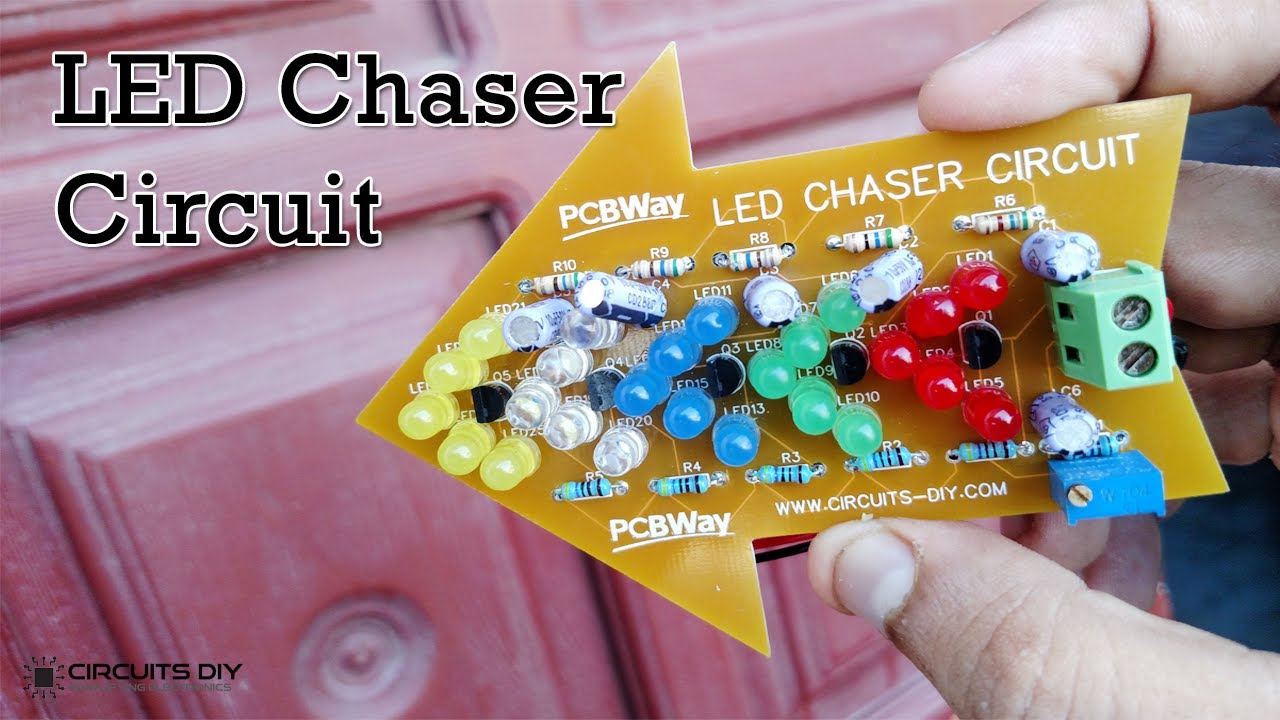
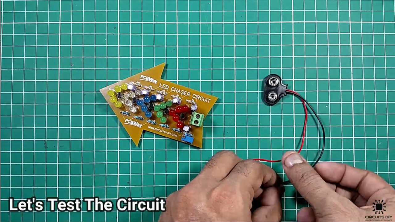
Would you like to learn how to make a led chaser circuit using some transistors? LED chaser circuits are simple electronic circuits that usually find their use in advertisement and decorative purposes in places such as automobiles, Festivals & Home decor. So, in this project, we will design a “LED Chaser Circuit using 2SC9013 NPN transistors”.
This LED Chaser Circuit consists of Multiple LEDs (25) every transistor is responsible to drive 5 LEDs. The heart of this circuit is the shape of this PCB. There are ways to create a PCB at home, but they require the use of chemicals, and normally the final result is not perfect, and is tedious work to create several identical ones. So the proper solution is to order the manufacturing of the PCB.
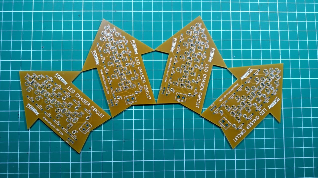
PCBWay commits to meeting the needs of its customers from different industries in terms of quality, delivery, cost-effectiveness, and any other demanding requests. As one of the most experienced PCB manufacturers in China. They pride themselves to be your best business partners as well as good friends in every aspect of your PCB needs.
Hardware Components
The following components are required to make LED Chaser Circuit
| S.no | Components | Value | Qty |
|---|---|---|---|
| 1. | Transistors | 2SC9013 | 5 |
| 2. | LED’s | – | 25 |
| 3. | Heat Sink | – | 1 |
| 4. | Potentiometer | 10K | 1 |
| 5. | Electrolytic Capacitor | 100uf | 6 |
| 6. | Resistors | 4.7k, 560, 1k | 6, 6, 1 |
| 7. | Battery | 9v | 1 |
| 8. | Breadboard | – | 1 |
| 9. | Connecting Wires | – | 1 |
2SC9013 Pinout
For a detailed description of pinout, dimension features, and specifications download the datasheet of 2SC9013
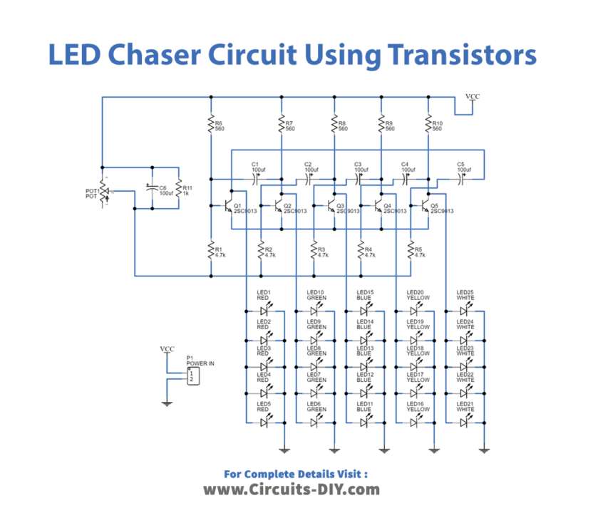
LED Chaser Circuit
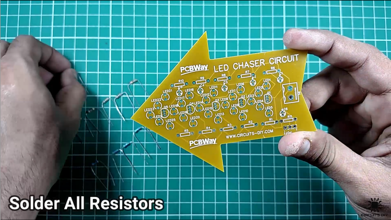
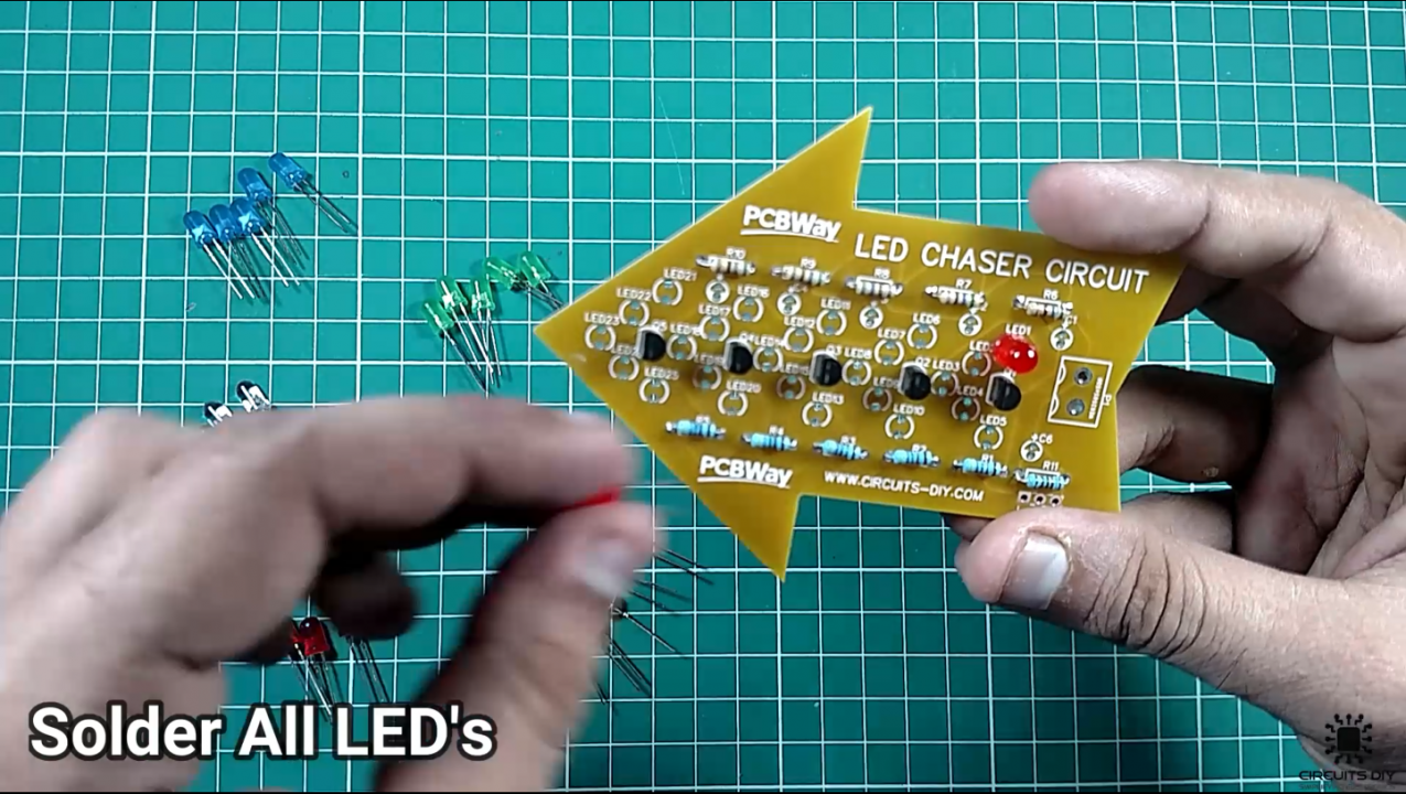
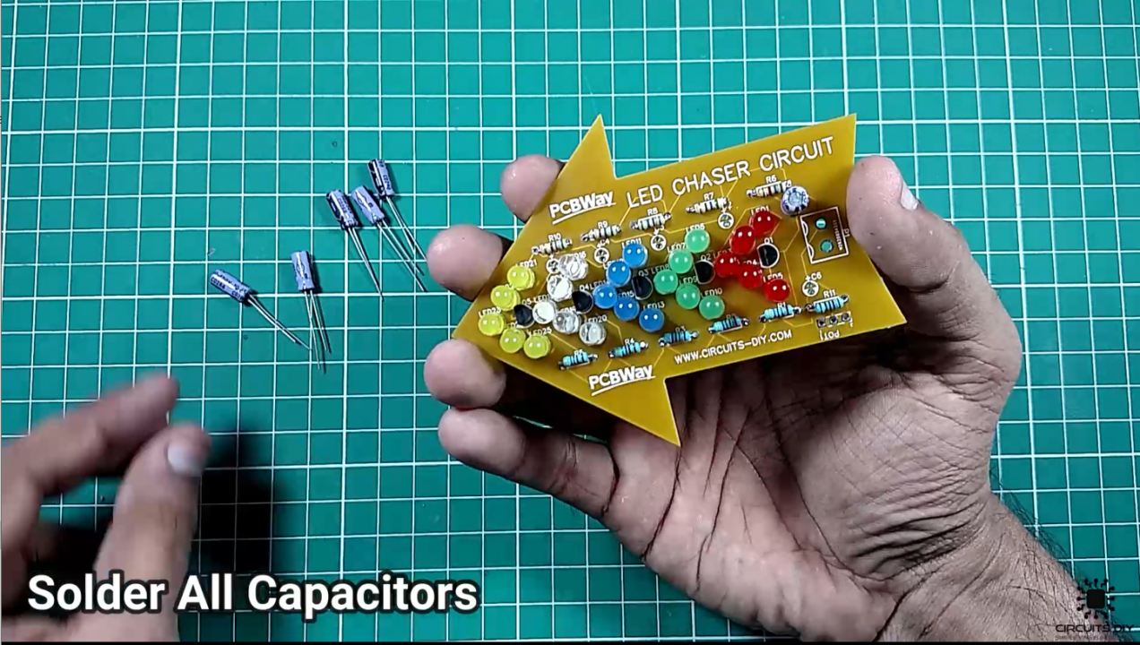
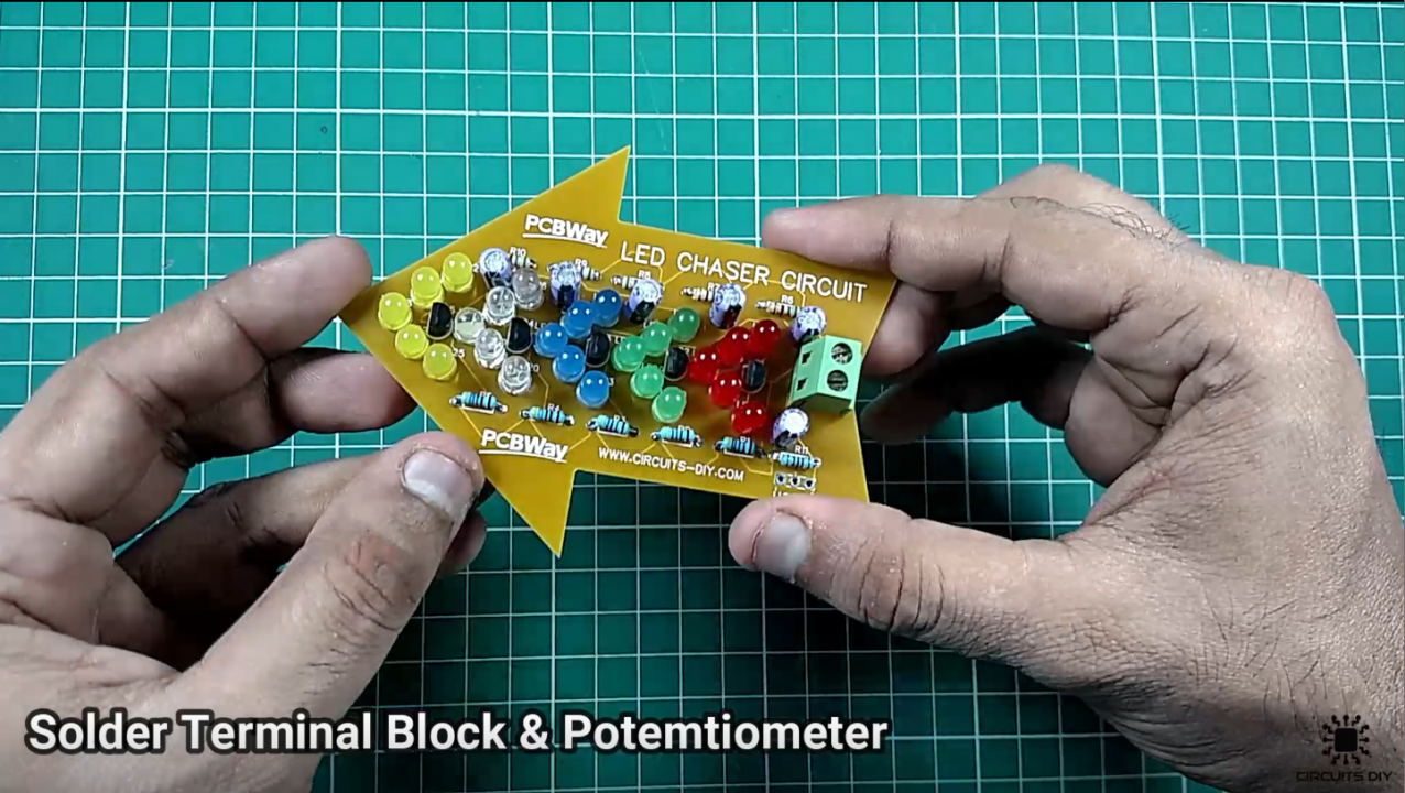
Useful Steps
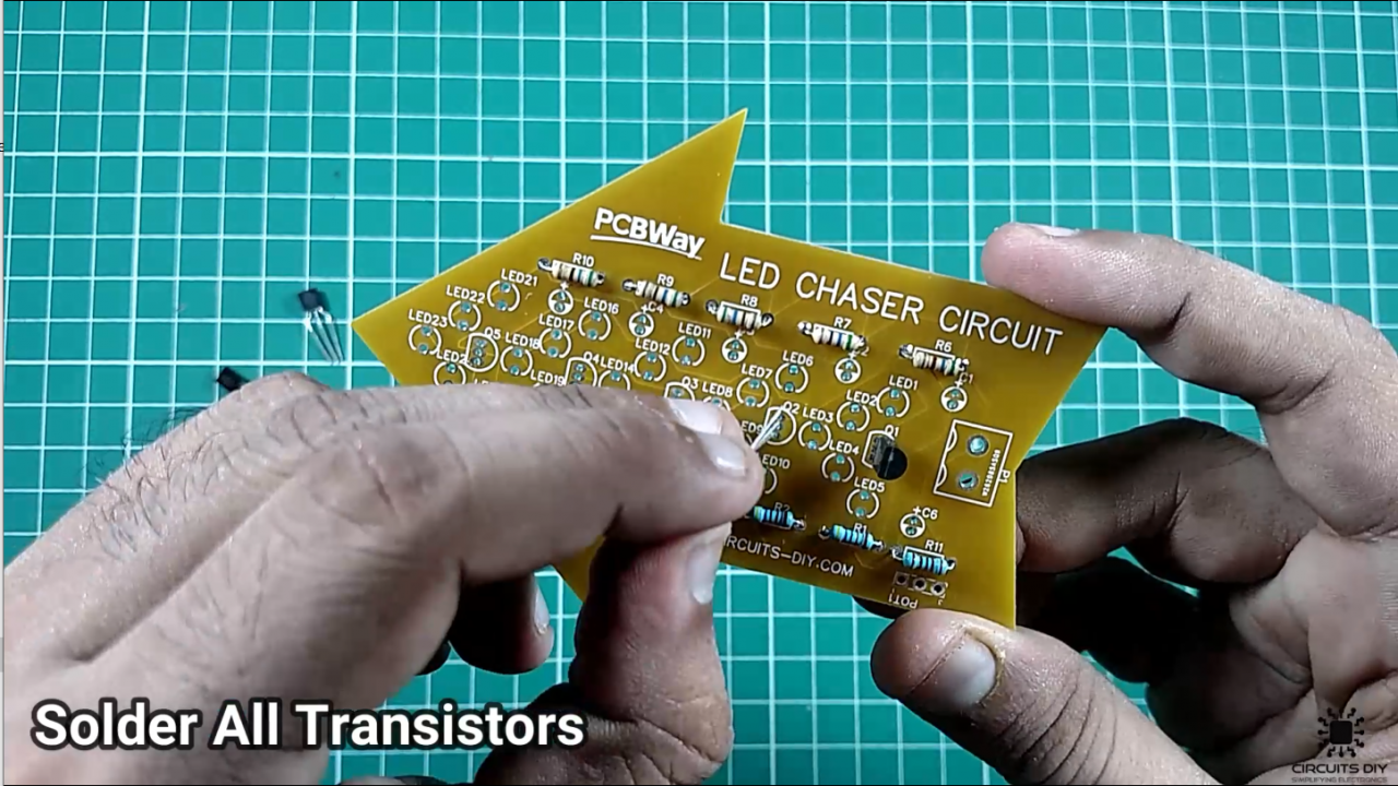
Working Explanation
The main component of this circuit is the 2SC9013 Transistor array. On powering on the DC signal triggers the base of the transistor Q1, Lighting up the first array of 5 Red LEDs. After which the collector output of Q1 acts as the control signal at the base of transistor Q2, which lights up the 2nd array of green LEDs after a set period of delay due to a 100uF Capacitor.
Now the Output DC signal triggers the base of transistor Q3 which in turn activates the blue LED array after a delay. Subsequent to this the yellow and white LED array also lights up after a delay introduced by the 100uF capacitors. This circuit can easily be operated by using a 9V/5V DC Supply.
Applications
- Useful in various projects such as Light Chaser, Remote controlled Switch, Alarm, Touch ON-OFF switch, Clap switch, Matrix Die.


2 thoughts on “LED Chaser Circuit using Transistors – Electronics Projects”
Comments are closed.