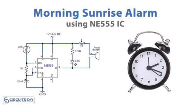
The clap switch circuit is yet another simple and remarkable project. This is a simple electronic project and is mostly used to turn ON and OFF AC appliances with the help of sound. It consists of a condenser mic to pick the sound of the clap and convert it from sound energy to electrical energy which is then used to trigger 555 timer output where LED is connected. So in this tutorial, we are going to make a simple step-by-step “Clap Switch Circuit using 555 Timer IC”
The main component of this circuit is a NE555 Timer IC. The IC possesses an oscillation frequency ranging from 670 to 680 Hz. Here, this NE555 timer acts as a monostable multivibrator. A monostable multivibrator (MMV) often called a one-shot multivibrator, is a pulse generator circuit in which the duration of the pulse is determined by the R-C network, connected externally to the555 timers. In such a vibrator, one state of output is stable while the other is quasi-stable (unstable). For an auto-triggering output from a quasi-stable state to a stable state, energy is stored by an externally connected capacitor to a reference level. The time taken in storage determines the pulse width.

Hardware Components
The following components are required to make Clap Switch Circuit
| S. No | Component | Value | Qty |
|---|---|---|---|
| 1 | Condenser Mic | 1 | |
| N2 | IC | NE555 Timer | 1 |
| 3 | Transistor | BC547 | 1 |
| 4 | Resistors | 220, 1k, 47k, 10k | 1 |
| 5 | Electrolytic Capacitor | 10uf | 1 |
| 6 | LED | 1 | |
| 7 | Battery 5-9 Volt with Clip | 1 | |
| 8 | Breadboard | 1 | |
| 9 | Connecting Wires | 12 |
555 Timer Pinout

For a detailed description of pinout, dimension features, and specifications download the datasheet of 555 Timer
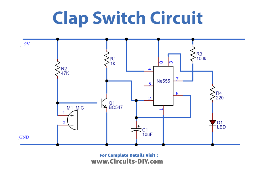
Clap Switch Circuit Diagram
Working Explanation
When we produce some sound near the condenser mic, the sound converts into electrical energy and raises the potential at the base of the transistor, which will turn the transistor Q1 ON.
As soon as the transistor becomes ON, the potential would become low, triggering the 555 IC because of the low voltage (below Vcc/3) at TRIG Pin 2. So the output PIN3 will be high and a positive clock pulse will be applied on the internal Flip-flops, making Flip-flop respond and the LED turn ON. This SET state of flip flop will remain as it is until the next clock pulse.
Applications
- Being not just restricted to turning LEDs ON and OFF, A clap switch circuit can also be used in any electric appliances such as a Fan, Radio, or any other basic circuit which you want to turn ON by using a Sound.