
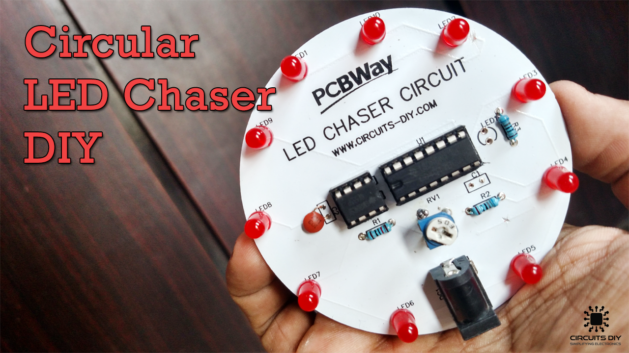
A circular LED chaser is a simple electronic sequencer usually designed by combining a clock-generating device with a counter. the input clock can be of any type such as an astable multivibrator, an inverter, logic gates, a pushbutton, or a dedicated timer IC. The counter can be any of several types including 4-bit, 8-bit, decade, or shift registers, depending on the number of outputs and other features. So, In this project, we are going to build a simple Circular LED chaser circuit using a CD4017 Decade counter IC.
CD4017 IC is a 16-pin CMOS decade counter/Divider with 10 outputs. It is also known as the ‘Johnson 10 stage decade counter’. It has 10 decoded outputs that give output signals one by one in sequence when a clock signal from the clock input is given.
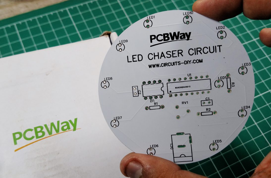
PCBWay commits to meeting the needs of its customers from different industries in terms of quality, delivery, cost-effectiveness, and any other demanding requests. As one of the most experienced PCB manufacturers in China. They pride themselves to be your best business partners as well as good friends in every aspect of your PCB needs.
Hardware Components
The following components are required to make Circular LED Chaser Circuit
| S. no | Component | Value | Qty |
|---|---|---|---|
| 1. | Decade Counter IC | CD4017 | 1 |
| 2. | LEDs | – | 11 |
| 3. | IC | NE555 Timer | 1 |
| 4. | Potentiometer | 10K | 1 |
| 5. | DC power jack | 3.5mm | 1 |
| 6. | Capacitors | 1µF, 0.01µF | 1 |
| 7. | Resistors | 10K, 680 | 1, 2 |
| 8. | Battery | 9V | 1 |
| 9. | Battery clips | – | 1 |
| 10. | Breadboard | – | 1 |
| 11. | Connecting Wires | – | 1 |
555 IC Pinout

For a detailed description of pinout, dimension features, and specifications download the datasheet of NE555
CD4017 Pinout
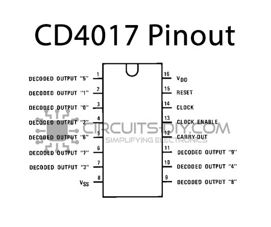
For a detailed description of pinout, dimension features, and specifications download the datasheet of CD4017
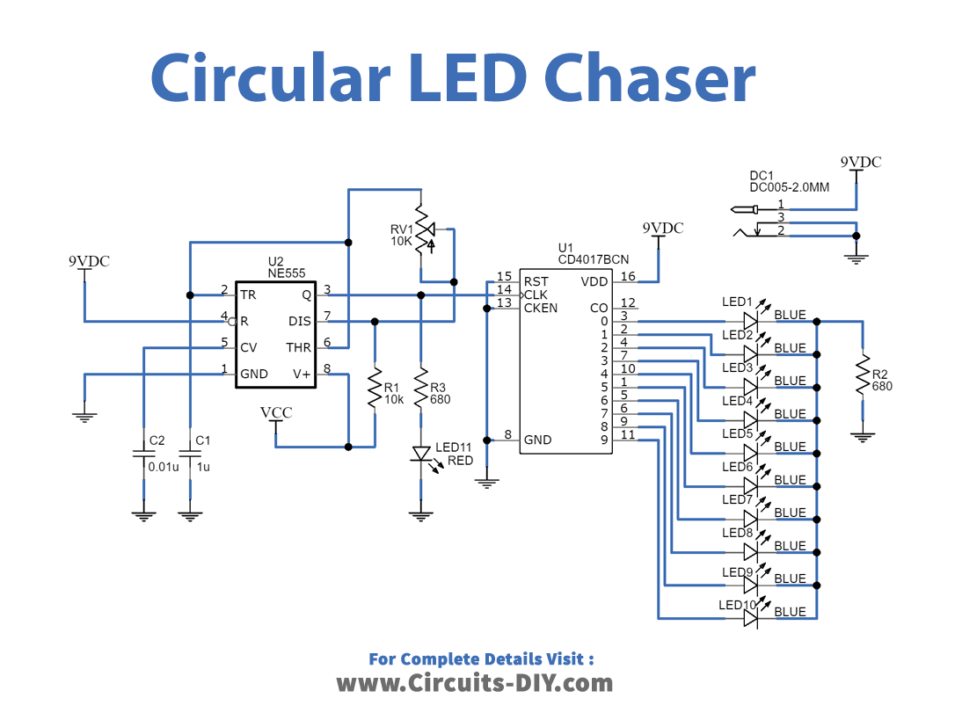
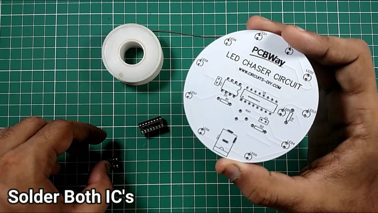
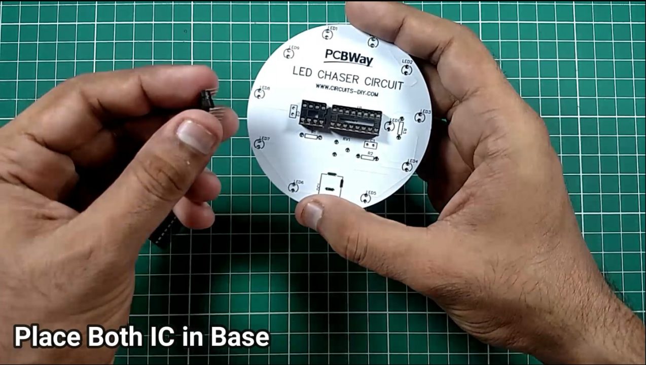
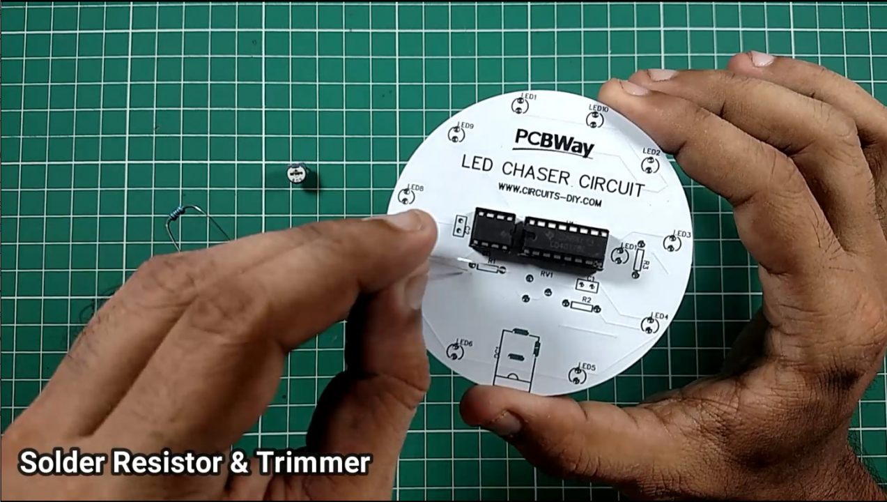
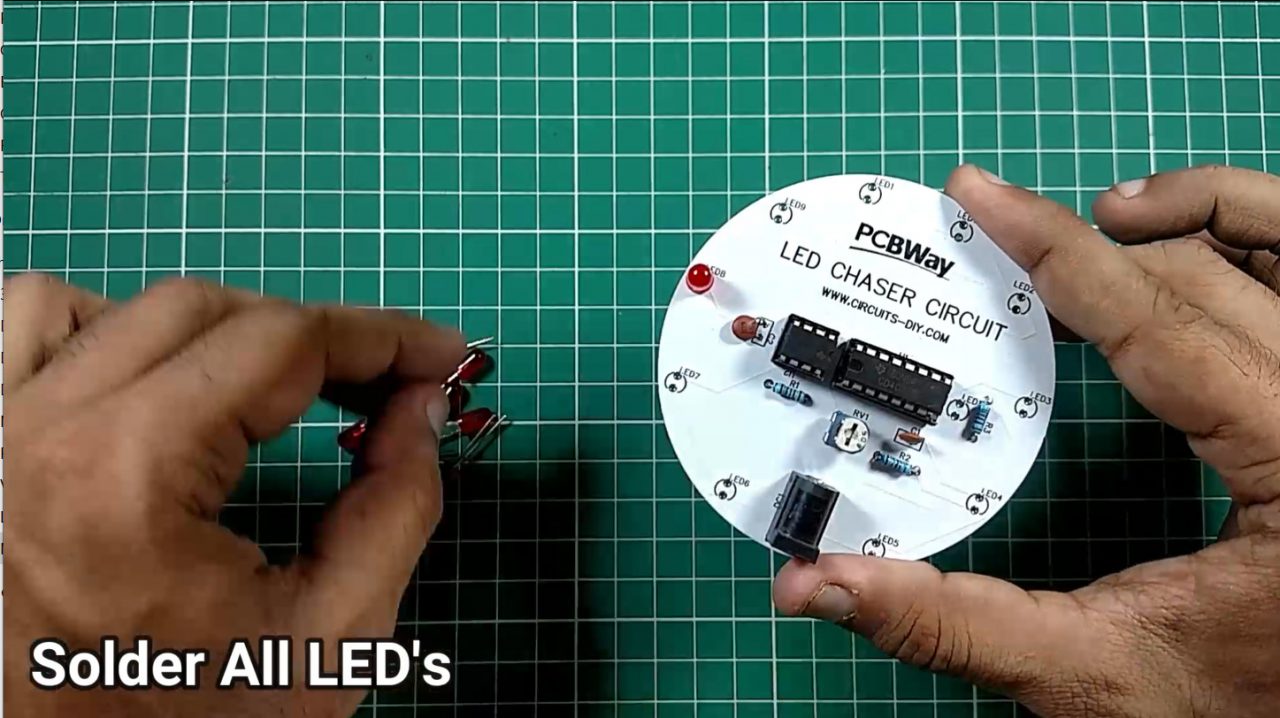
Circular LED Chaser Circuit
Steps

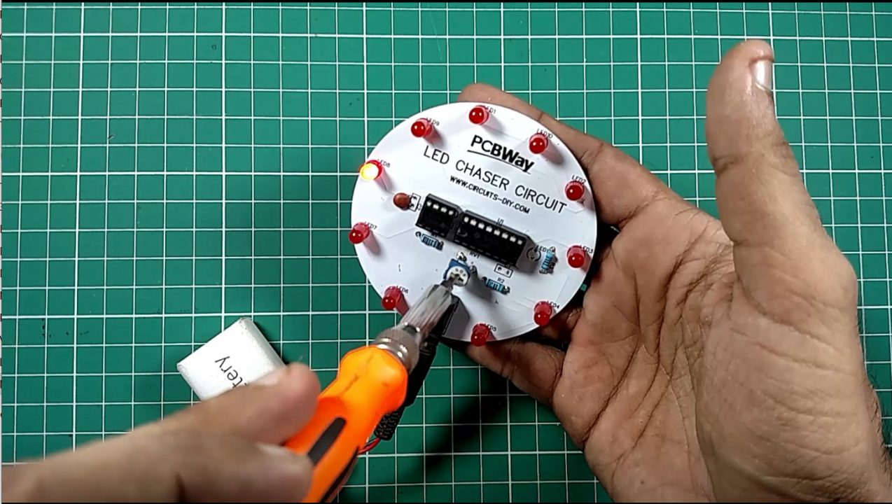
Working Explanation
A NE555 timer is connected to the clock input of the CD4017 decade counter IC. The timer IC provides the CLK input of the decade counter with square wave input. CD4017 has 10 output pins and each pin joins to an LED. By default, the first output pin is on or high and the rest are off.
Each time the clock input pin of 4017 IC detects a rise in voltage (from low to high), it turns off the current output and turns on the next sequential output. This swapping of outputs which looks like the LEDs are chasing each other, continues until the last LED and then the output resets back to the first LED.
Applications
- Widely used in places such as advertising displays and in running-light ‘rope’ displays in small discos, etc.
- Useful in various projects such as Light Chaser, Remote controlled Switch, Alarm, Touch ON-OFF switch, Clap switch, Matrix Die.
Related posts:
 How to Control RGB LED Wirelessly using ESP8266 ESP01
 Simple ESP8266 Weather Station with BME280
 How To Make Multi-Color RGB LED Light At Home - DIY
 Automatic Street Night Light Circuit Using LDR | DIY Project
 Heart Rate Pulse Sensor - BPM Meter using OLED & ESP32
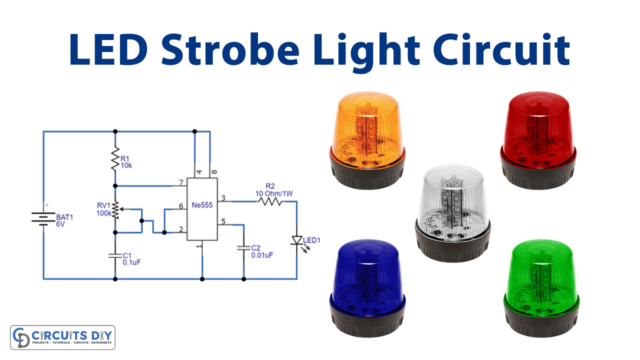 High Intensity LED Strobe Circuit IC 555


1 thought on “Circular LED Chaser using 555 timer & CD4017 – Electronics Projects”
Comments are closed.