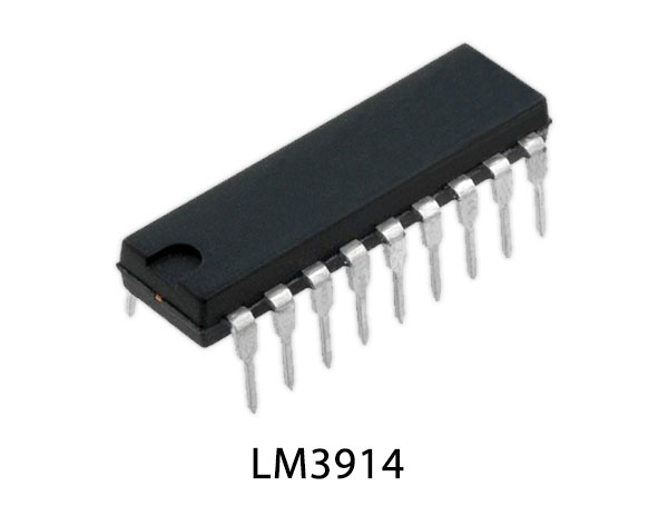
A VU meter or a volume unit meter is a device that displays the intensity of an audio signal in music equipment (loudspeaker, mic, electric guitars, amps, etc.). More specifically, it is used to visualize analog signals. In this project, we are going to design a simple VU meter using the LM3914 dot/bar display driver IC.
LM3914 is an analog-controlled LED driver IC, meaning it can control (turn on or off) 10 LEDs by an analog input voltage. This IC eliminates the need for programming a microcontroller and also reduces the hardware required to control 10 LEDs. For LM3914, the input voltage can vary from 3V to 18V. The IC has two operating modes DOT mode and BAR mode, also more than one IC can be cascaded to control up to 100 LEDs. Since the LEDs can be controlled without any flickering and perform flawlessly with equal brightness these ICs are commonly used in visual alarms and other metering or monitoring applications.

Hardware Components
The following components are required to make VU Meter Circuit
| S.no | Component | Value | Qty |
|---|---|---|---|
| 1. | Breadboard | – | 1 |
| 2. | Connecting Wires | – | 1 |
| 3. | Battery | 9v | 1 |
| 4. | LED Driver IC | LM3914 | 1 |
| 5. | LED | 5mm | 10 |
| 6. | Condenser MIC | – | 1 |
| 7. | Audio Jack (Female) | 3.5mm | 1 |
| 8. | Diodes | 1N4148 | 1 |
| 9. | Toggle Switch | – | 1 |
| 10. | Electrolyte Capacitor | 1uF | 2 |
| 11. | Resistor | 10k, 3.9k, 2.9k | 1, 1, 1 |
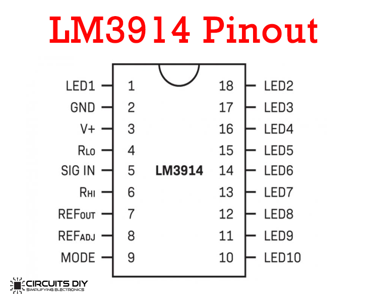
LM3914 Pinout

For a detailed description of pinout, dimension features, and specifications download the datasheet of LM3914
VU Meter Circuit

Working Explanation
The heart of the circuit is an LM3914 LED driver IC. Firstly, the analog input is coming from a mic/smartphone. The 1μF capacitor (C1) stops the DC component of the transmission, allowing the AC input from the microphone to enter the SIGNAL pin of the IC. These filtered MIC signals go to the voltmeter LM3914. The LM3914 comparator glows the LEDs according to the strength of the given signal. The reference voltage at Pin 7 is set by two resistors that are connected at the Ref (ADJ) pin of LM3914. The formula regarding Output Reference Voltage is given as:
REF(OUT) V = 1.25 x (1+ R2/R1)
The IC can operate in two different modes, one is the dot mode and the other is bar mode. In Dot mode, the MODE pin (pin 9) is open by using a toggle switch, in this mode, only one LED will turn on depending on the input voltage. In Bar mode, the mode pin (pin 9) connects to the V+ pin and the LED will turn on or turn off sequentially based on the input voltage.
Applications
- Most commonly used in the music industry for procedures such as live music production & recording.
- It can be reverse-engineered to work as a power level indicator for various energy storing devices such as batteries and dry cells.


