In this article
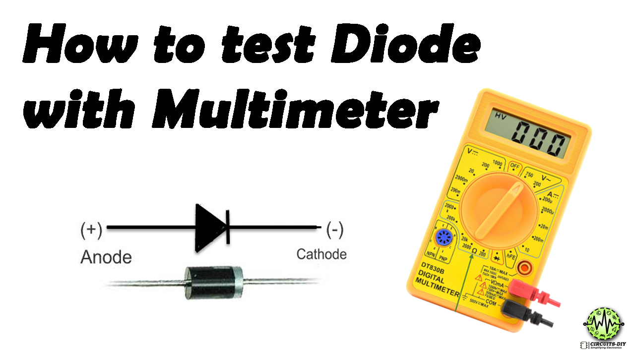
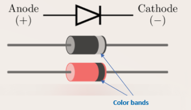
Before testing the diode, we have to identify the anode and cathode terminals of the diode. Most diodes have a white band on its body and this white-band side terminal is the cathode. Some diodes might have different color bands, but the colored band side is always cathode.
Method 1 (How to test diode)
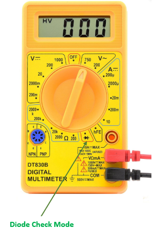
- In most digital multimeters there is a diode check mode. To enable this mode, rotate the central knob to the place where the diode symbol is indicated.
- Connect the red probe of the multimeter to the anode and connect the black probe to the cathode of the diode.
- Observe the reading on the multimeter. If you are using a silicon diode then the reading should be between 0.6 to 0.7. For the germanium diode, this value should be between 0.25 to 0.3.
- Now to check the reverse bias configuration of the diode, connect the red probe to the cathode and black probe to the anode. Since diode is designed to prevent current flowing in reverse bias condition, so the meter should read OL (Overload) which is equivalent to the open circuit if the diode is working perfectly.
Method 2 (How to test diode)
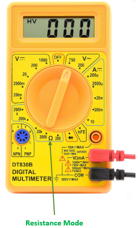
- Select the resistance or ohmmeter mode (marked with the ohm symbol Ω) on the multimeter by rotating the central knob. Choose a low range, such as 1KΩ or 20KΩ.
- Connect the red probe of the multimeter to the anode and connect the black probe to the cathode of the diode, this means diode is now forward biased. A working diode will have a low resistance value (usually below 1kΩ) in this direction
- Now to check the resistance in reverse bias configuration, rotate the knob and select a high resistance value of 200KΩ or higher. Reverse the connection of the probe by connecting the red probe to cathode and black to the anode.
- Since in reverse biased condition, diode offers very high resistance. Hence the meter indicates OL (Overload) or a very high resistance if the diode is working properly.