
A Panic alarm is a simple electronic circuit that allows a person under stress to quickly & safely call for help in case of an emergency. Panic alarms also go by the names of duress alarms, hold-up alarms, or panic buttons.
Panic alarms are used when it may be unsafe or uncomfortable to call for help in other ways. For example, if a potentially dangerous person is standing in your lobby, it may be unwise to further escalate the situation by picking up a phone to call for assistance. There they can provide a quick & convenient way to call for help without drawing attention. In this project, we are going to step-by-step design a Simple Panic alarm using a NE555 timer IC.

Hardware Components
The following components are required to make Panic Alarm Circuit
| S.No | Component | Value | Qty |
|---|---|---|---|
| 1. | Breadboard | – | 1 |
| 2. | Battery | 9v | 1 |
| 3. | Connecting Wires | – | 1 |
| 4. | IC | NE555 Timer | 1 |
| 5. | NPN Transistor | BC547 | 1 |
| 6. | Ceramic Capacitor | 0.01uF | 1 |
| 7. | Resistors | 10k, 1k | 2,2 |
| 8. | LED | 5mm | 1 |
| 9. | Buzzer | – | 1 |
| 10. | Push Buttons | – | 2 |
555 IC Pinout

For a detailed description of pinout, dimension features, and specifications download the datasheet of 555 Timer
Panic Alarm Circuit
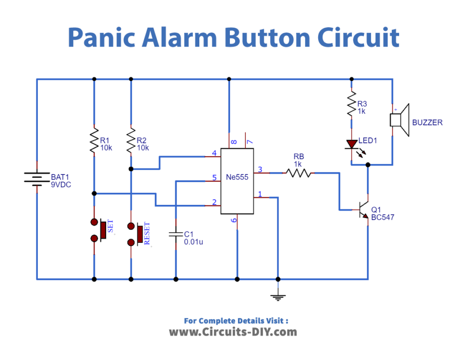
Connections
- Place NE555 timer IC on the center junction of the breadboard.
- Join Pin No. 8 (Vcc) with the positive rail of the 9V supply and Pin No. 1 (GND) with the ground rail.
- Connect SET & RESET pushbuttons to the positive rail of the supply via a 10KΩ resistor & Connect their other terminals with the ground of the supply respectively.
- join one terminal of a 0.01μF capacitor with Pin no.5 (CONT) & ground the other terminal.
- Connect Pin No. 6 (THRES) to the output of the 0.01μF capacitor.
- Connect Pin No. 2 (TRIG) & Pin No. 4 (RESET) with SET & RESET pushbuttons respectively.
- Connect the -ve terminal of the LED with the collector terminal of a BC547 NPN transistor & connect the +ve terminal of the LED to the positive rail of the supply via a 1KΩ resistor.
- Join the emitter of the BC547 transistor with the ground rail.
- Connect the base terminal of the transistor with Pin No. 3 (OUT) of the timer IC.
- Connect the 9V battery with the power rails of the breadboard, minding the order of negative & positive sides of the rails.
Working Explanation
Resistors R1 & R2 pull up TRIG pin 2 & RESET pin 4. On pressing the SET pushbutton, trigger pin 2 turns low. Therefore, making the output of the lower comparator inside the 555 timer IC go high for an instant. This sets the flip-flop & the OUT pin goes high & remains in this state until an external reset signal is provided. The process of resetting the 555 timer IC is done by pressing the RESET button. This makes the RESET pin go low (less than Vcc/3) for an instant which is connected directly to a flip-flop through a transistor. Hence, the flip-flop is reset & the output becomes low and stays in this state until the next trigger is given.
The output signal reaches the base terminal of Q1 (BC547) & the transistor turns ON. Also, turn ON the Buzzer & the LED connected to the transistor. BC547 NPN transistor is a current-controlled device. This transistor is used as a control switch whose control signal is provided by the NE555 IC.
Application
- Commonly used in high-risk areas such as security stations, police stations & checkpoints.
- An important security feature in sensitive workplaces such as bank vaults & military compounds.
- An integral part of home security systems & Office suites.


1 thought on “Simple Panic Alarm Circuit – Using NE555 Timer IC”
Comments are closed.