What is a Timer?
A Timer is a control device that outputs a signal at a preset time after an input signal is received. So in this tutorial, we are going to make a “Time Delay Timer Circuit using 555 Timer IC”. This circuit consists of 2 switches one for starting the delay time and the other for resetting. It also has a potentiometer to adjust the time delay, where you can increase or decrease the time delay by just rotating the potentiometer.
The main component of this circuit is a NE555 Timer IC. The IC possesses an oscillation frequency ranging from 670 to 680 Hz. Here, this NE555 timer acts as a monostable multivibrator. A monostable multivibrator (MMV) often called a one-shot multivibrator, is a pulse generator circuit in which the duration of the pulse is determined by the R-C network, connected externally to the 555 timers. In such a vibrator, one state of output is stable while the other is quasi-stable (unstable). For auto-triggering of output from a quasi-stable state to a stable state, energy is stored by an externally connected capacitor to a reference level. The time taken in storage determines the pulse width.

Hardware Components
The following components are required to make Time Delay Circuit
| S.No | Component | Value | Qty |
|---|---|---|---|
| 1 | Breadboard | – | 1 |
| 2 | Battery | 9v | 1 |
| 3 | IC | NE555 Timer | 1 |
| 4 | Resistors | 100k, 10k, 220 | 1, 1, 1 |
| 5 | LED | 5mm | 1 |
| 6 | Push Button | – | 1 |
| 7 | Capacitor | 0.01uF | 1 |
555 Timer Pinout

For a detailed description of pinout, dimension features, and specifications download the datasheet of 555 Timer
Time Delay Circuit
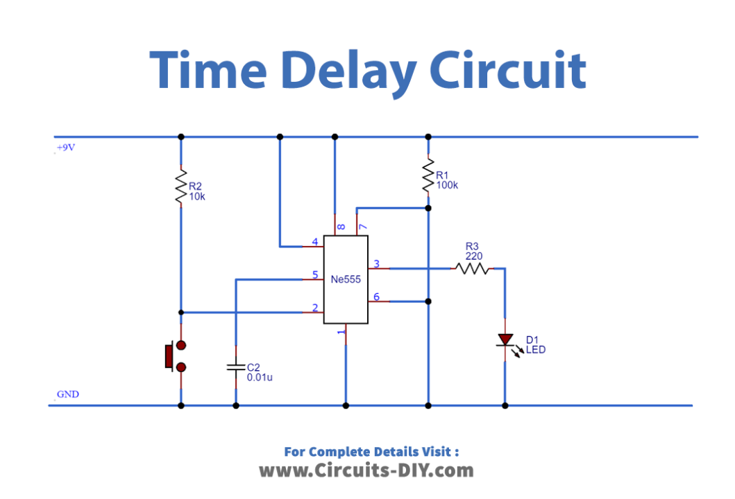
Working Explanation
Initially, when no button is pressed, the output of the 555 IC remains LOW and the circuit remains in this state until you press the pushbutton and the capacitor remains in discharged condition.
When the pushbutton is pressed, the countdown timer starts and the green LED turns on after the particular time (defined by the formula T= 1.1*R1*C1) the 555 timer goes into a stable state, where the Red LED turns ON and the green LED turns Off. You can increase and decrease the time delay by using the 100K potentiometer.
Application
- It commonly serves as a protection circuit to protect any electrical or electronic equipment and appliance from sudden high or unstable voltage such as a voltage stabilizer for the fridge, UPS & PCs.