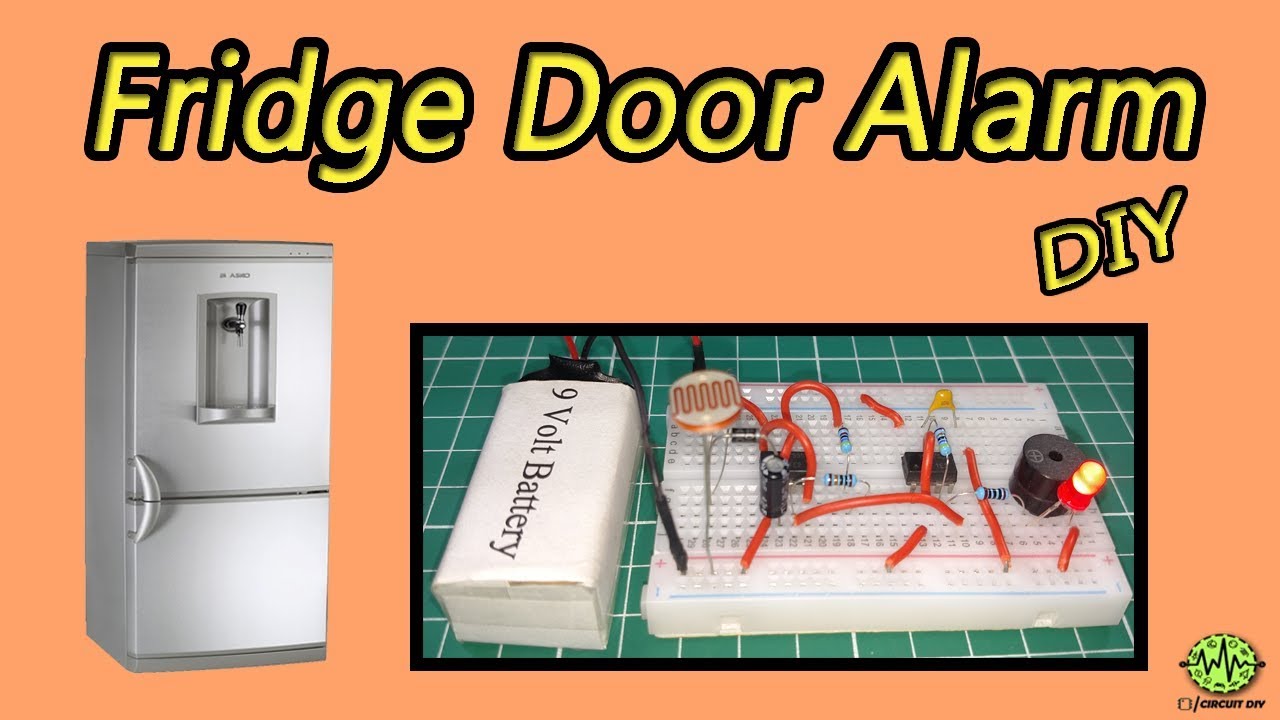
The fridge door alarm circuit is used to sense the status of the door opening OR closing. When the door opens for a long time this circuit triggers the 555 timer output and produces a highly alarming sound. This circuit is very important because growing up children most of the time try to open the door and they are left open. So today in this tutorial I am going to show how to make a simple fridge door alarm circuit using 555 timer IC so let’s get started from the video below.
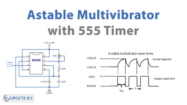
The heart of this circuit is a NE555 Timer IC. The IC possesses an oscillation frequency ranging from 670 to 680 Hz. Here, this NE555 timer acts as an astable multivibrator An astable multivibrator is a free-running oscillator that switches continuously between its two unstable states. With no external signal applied, the transistors alternately switch from cutoff to saturation state at a frequency that RC time constants of the coupling circuit determine. If these time constants are equal (R and C are equal) then a square wave will generate with a frequency of 1/1.4 RxC. Hence, an astable multivibrator is also a pulse generator or a square wave generator.

Hardware Components
The following components are required to make Fridge Door Alarm Circuit
| S.No | Component | Value | Qty |
|---|---|---|---|
| 1. | Breadboard | – | 1 |
| 2. | Battery | 9v | 1 |
| 3. | LDR | – | 1 |
| 4. | IC | NE555 Timer | 2 |
| 5. | Diode | 1N4007 | 1 |
| 6. | Buzzer | – | 1 |
| 7. | Ceramic Capacitor | 0.1uF, 47uF | 1, 1 |
| 8. | Resistors | 10k, 470k, 100k, 100 | 1, 2, 1, 1 |
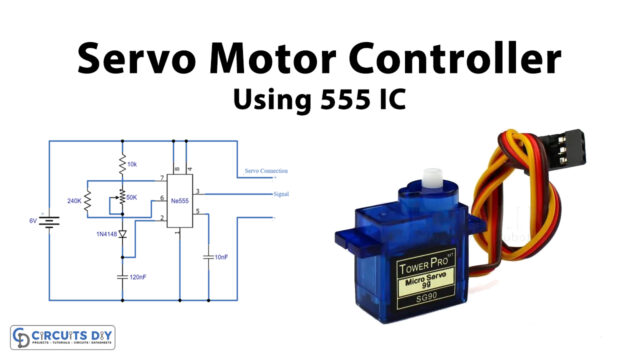
555 IC Pinout

For a detailed description of pinout, dimension features, and specifications download the datasheet of 555 Timer
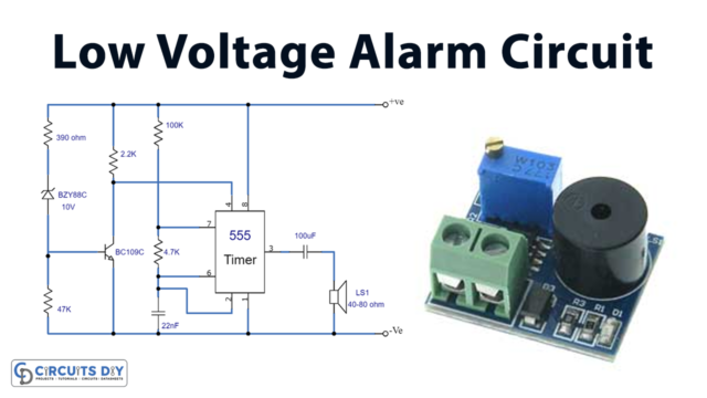
Fridge Door Alarm Circuit
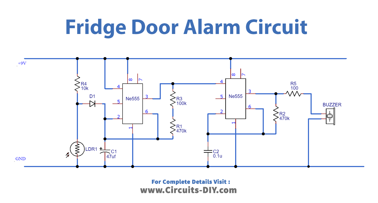
Working Explanation
When the fridge door is closed, the resistance of the LDR is almost 1MὨ. The output voltage of the potential divider appears across the capacitor and it remains in charged condition (Voltage greater than 2/3Vcc) making the output LOW. When the Fridge door is open, the light falls over LDR which lowers the resistance of LDR and causes the capacitor to discharge. After this (Voltage lower than 2/3Vcc), the output starts to oscillate at a certain frequency and the output is HIGH. Again, the capacitor charges and reaches a threshold continued by the discharge of the capacitor. This continues till the LDR resistance goes high which happens in the absence of light.
Now, the second NE555 timer IC starts to oscillate and the output switches between HIGH & LOW causing the connected buzzer to beep in a fluctuating pattern which is combinational because of the oscillations of the first timer and the second timer’s internal oscillation. During the HIGH condition of the first timer output, the second timer RESET will trigger. Thus, the capacitor C2 charges (Voltage higher than 2/3Vcc), and output go LOW. In a short time span, the capacitor starts to discharge (Voltage lower than 2/3Vcc) causing the output to HIGH. Hence, the buzzer connected to the output generates a beeping sound.
Applications
- Commonly used in appliances such as fridges, freezers & beverage coolers to ensure that the appliance is not left open for too long by accident.