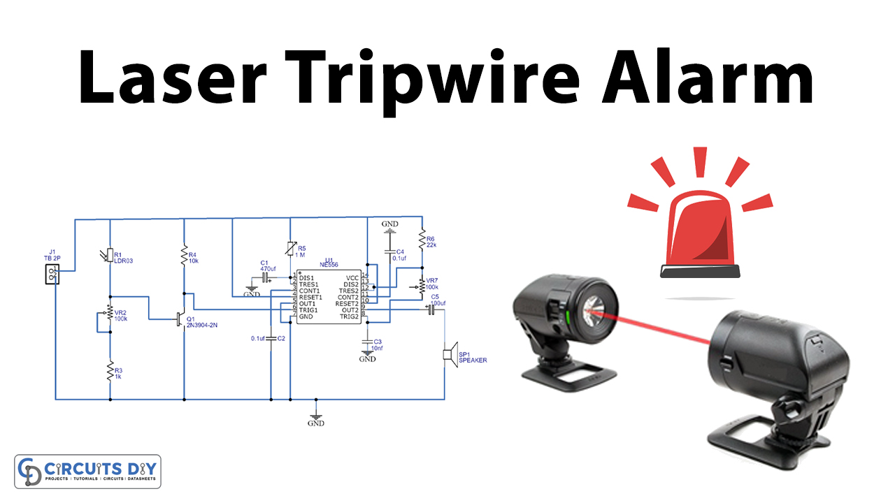
Laser Tripwire alarm can detect the movement of people or objects while they are passing through the laser beam and trigger security alarms as alert signals to those concerned. It is an important component of home security & security details for high-profile properties. In this project, we are going to design a simple Laser tripwire alarm circuit using a NE556 precision dual timer IC.
The NE556 timer is a dual version of the 555 timer IC. In other words, it is embedded with two 555 timers operating separately. The CMOS versions offer improved characteristics for particular applications. The two timers operate independently of each other sharing only Vs and ground. The circuit may be triggered and reset on falling waveforms. The 556 timer is a 14-pin configuration. Each Timer is provided with its own threshold, trigger, discharge, control, reset and output pins. This IC can be used for both the oscillator as well as pulse generator due to the availability of two separate 555 timers.
Hardware Component
The following components are required to make Laser Tripwire Alarm Circuit
| S.no | Component | Value | Qty |
|---|---|---|---|
| 1. | Breadboard | – | 1 |
| 2. | Connecting Wires | – | 1 |
| 3. | Battery | 9v | 1 |
| 4. | Dual Timer IC | NE556 | 1 |
| 5. | Laser Diode | – | 1 |
| 6. | LDR | – | 1 |
| 7. | Transistor | 2N3904 | 1 |
| 8. | Speaker | 8 ohm | 1 |
| 9. | Potentiometer | 1M, 100k | 1,1 |
| 10. | Resistor | 22k, 10k, 1k | 1,1,1 |
| 11. | Capacitor | 470uF, 0.1uF, 100uF, 10uF | 1,1,1,1 |
NE556 Pinout
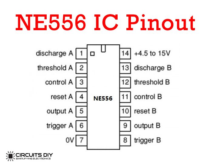
For a detailed description of pinout, dimension features, and specifications download the datasheet of NE556
Laser Tripwire Alarm Circuit
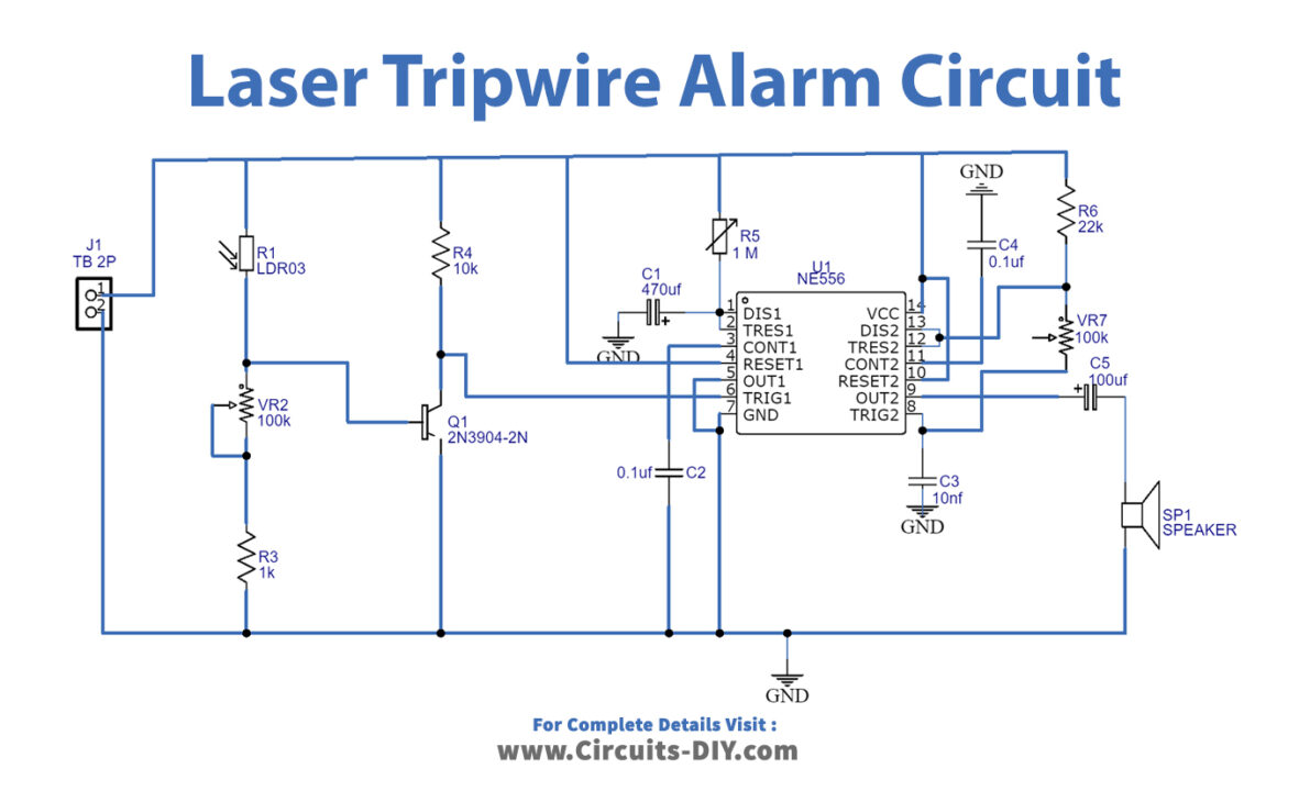
Working Explanation
The heart of the circuit is a NE556 Dual timer IC, both the timers (555 timers) are working separately in this circuit. The first section of the IC is working as a timer &and the second section is working as a buzzer circuit.
When any object comes in between the laser beam and the LDR, then the timer section of the circuit will become activated for a preset time period and will subsequently switch ON the buzzer circuit built around the second section of the 556 timer IC. The preset time period can be increased or decreased by changing the value of the 470μF capacitor. The time period for the timer section can be adjusted with the 1MΩ pot. The sound of the buzzer can be adjusted with the 100KΩ pot. The operating voltage of the circuit is 9V to 16V DC.
Applications
- An important part of home security setups.
- Commonly used in high profile/sensitive areas such as military bases, security vaults & supermax prisons.