A Heatbeat Sensor is a monitoring device that measures the heart rate i.e the speed of the heartbeat. A person’s heartbeat is the sound of the valves in his heart expanding or contracting as they force blood from one region to another There are two ways to monitor the heart rate: one way is to manually check the pulse either at the wrists or neck and the other way is to use a Heartbeat Sensor.
In this tutorial, we will show you how to design a circuit that can sense the heartbeat by using an LM358 IC along with an infrared transmitter and receiver. The IR transmitter in this circuit is an IR LED and the detector will be a photodiode.
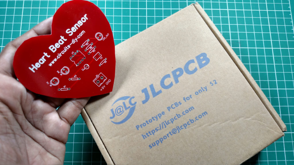
JLCPCB is the foremost PCB prototype & manufacturing company in china, providing us with the best service we have ever experienced regarding (Quality, Price Service & Time).
Hardware Components
The following components are required to make Heartbeat Sensor Circuit
| S. No | Components | Value | Qty |
|---|---|---|---|
| 1. | PCB | – | 1 |
| 2. | Op-Amp IC | LM358 | 1 |
| 3. | IR LED | – | 2 |
| 4. | Ceramic Capacitor | 100nF | 1 |
| 5. | Electrolytic Capacitor | 4.7uF | 1 |
| 6. | Resistors | 220 ohm, 10k, 680k, 6.8k, 47k | 2,1,1,1,1 |
| 7. | Battery | 9v | 1 |
| 8. | LED | 5mm | 1 |
LM358 Pinout

For a detailed description of pinout, dimension features, and specifications download the datasheet of LM358
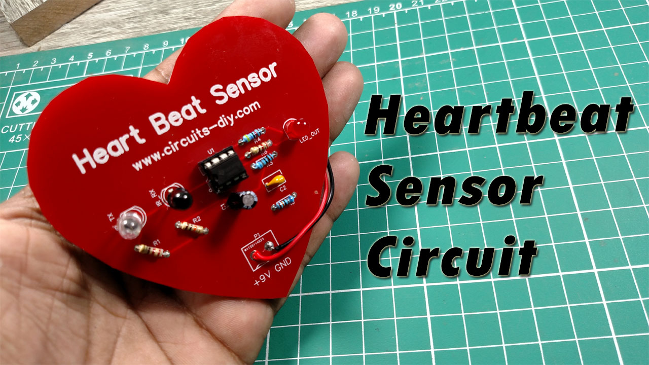
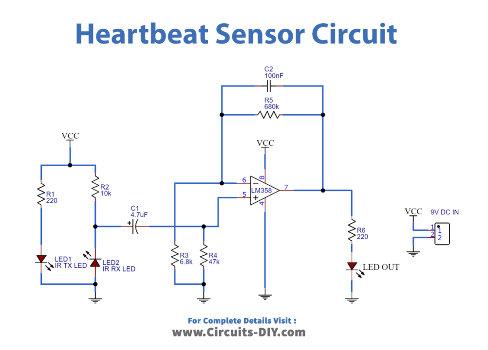
Heartbeat Sensor Circuit
Useful Steps
Follow all the steps carefully from the video tutorial
- Solder the base on LM358 IC to the PCB and connect the IC to the base.
- Solder all the LEDs to the PCB.
- Solder the Capacitors to the PCB.
- Solder the Resistors to the PCB.
- Solder the battery clip to the PCB.
- Connect the Battery and Test the circuit.
Working Explanation
Two IR photodiodes will sense the heart pulses in this circuit. One acts as a transmitter that shines light into or through your finger while the receiver measures how much light is reflected or absorbed. The measured intensity of the reflected rays depends on the heart pumping rate and on the difference in the oxygenated blood levels inside the blood content.
The IC used in this circuit is LM358 which has 2 op-amps on the same chip. The output of the photodiode is given to the non–inverting input of the first op-amp through a capacitor, which blocks the DC Components of the signal. The output of the first op-amp is then applied to one of the inputs of the second op-amp, which acts as a comparator. The LED is connected to the output of the second op-amp which can be obtained at pin 7. The rate at which LED flashes shows our heart rate.
Application
- Patient Health Monitoring System