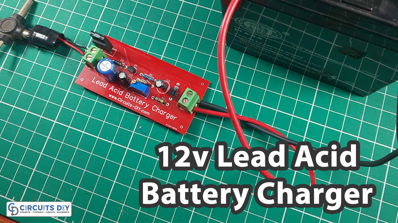
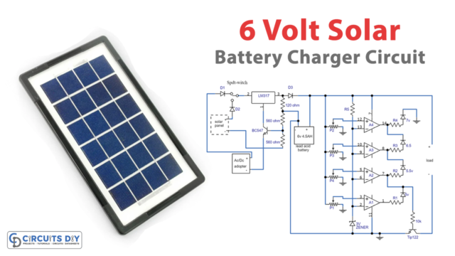
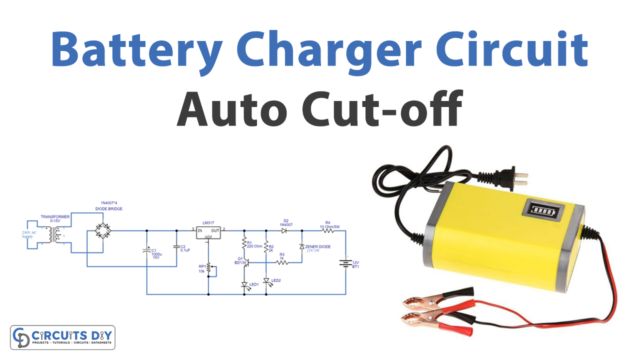
In this tutorial, I will tell you the best way to build a basic Lead Acid Battery Charger Circuit. This circuit utilizes to charge Rechargeable 12V Lead Acid Batteries with a rating in the scope of 1Ah to 7Ah. Lead Acid Batteries are one of the most established rechargeable batteries accessible today. Because of their cheap cost compare with new battery technologies and the capacity to give high current flows (a significant factor in cars), Lead Acid Batteries are as yet the favored selection of batteries in practically all vehicles.
Various batteries have various procedures for charging. And right now, I will tell you the best way to energize a lead-acid battery by utilizing a basic Lead Acid Battery Charger Circuit.
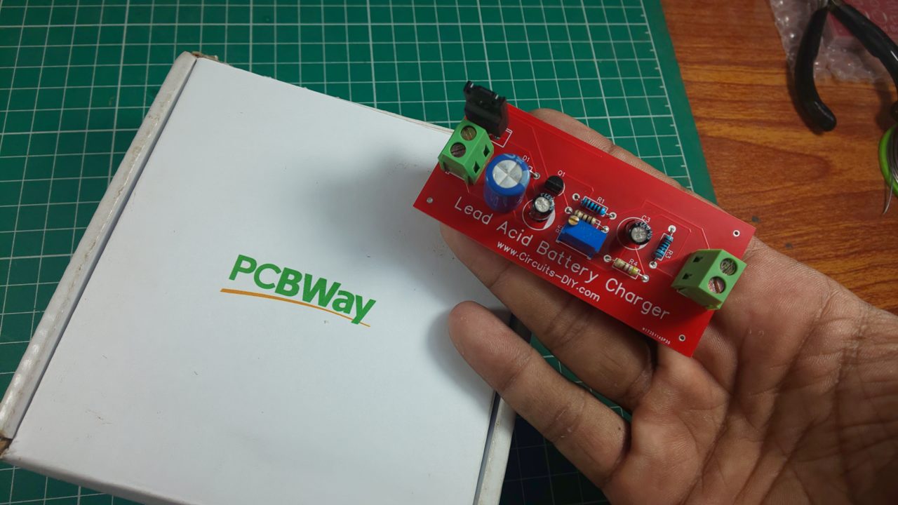
PCBWay commits to meeting the needs of its customers from different industries in terms of quality, delivery, cost-effectiveness, and any other demanding requests. As one of the most experienced PCB manufacturers in China. They pride themselves to be your best business partners as well as good friends in every aspect of your PCB needs.
Hardware Component
The following components are required to make a Lead Acid Battery Charger Circuit
| S.no | Component | Value | Qty |
|---|---|---|---|
| 1. | IC | LM317T | 1 |
| 2. | SLA Battery | 12V (Discharged) | 1 |
| 3. | Transistor | BC548 | 1 |
| 4. | Pot | 1K | 1 |
| 5. | Resistor | 0.5Ω, 100Ω, 120Ω, 470Ω | 1 |
| 6. | Electrolyte Capacitor | 0.22µF, 1000µF | 2, 1 |
| 7. | Battery | 15 – 18V | 1 |
LM317 Pinout
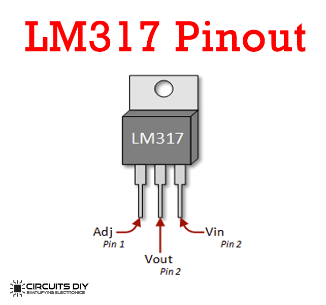
For a detailed description of pinout, dimension features, and specifications download the datasheet of LM317T
Lead Acid Battery Charger Circuit
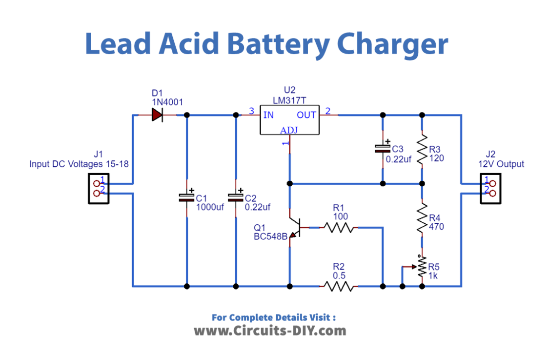
Working Explanation
The above circuit diagram is a lead-acid battery charger schematic. The main component of the circuit is the LM317 IC. The circuit gives the desired voltage to charge the 12V fixed lead-acid batteries or 12V SLA batteries. The charging current can be changed with a 1K potentiometer. This fixed lead acid battery charger circuit is programmed so you don’t need to focus on the battery to full charge in light of that the circuit naturally moves its capacity to stream charge when the battery becomes fully charged. Associate the battery which you need to accuse in an arrangement of a meter and change potentiometer to get the ideal charging current. Utilize a heat sink with IC, the input current ought to be at least 15V to get 12V yield output to charge the battery.


