
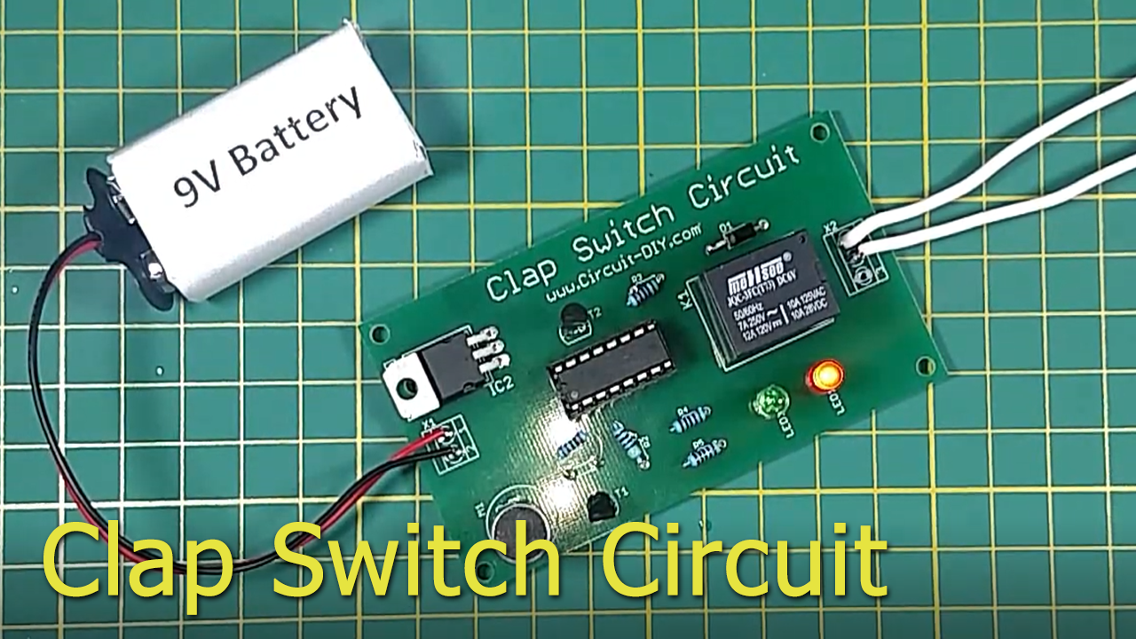
Clap switch circuits are simple circuits mostly used to fashion sound signals as electrical control signals. Electronics clap switches are used in places where dynamic control of machines/devices is preferred such as a sound-activated light responding to a knock on the door. So, in this project, we are going to design a simple DIY Clap Switch Circuit Using a CD4017 Counter IC.
The main component of this DIY Clap Switch Circuit is a CD4017 IC. A CD4017 IC is a 16-pin CMOS decade counter/Divider with 10 outputs. It is also known as the ‘Johnson 10 stage decade counter’. It has 10 decoded outputs that give output signals one by one in sequence when a clock signal from the clock input is given.
Hardware Components
The following components are required to make Clap Switch Circuit
| S.no | Component | Value | Qty |
|---|---|---|---|
| 1. | IC | CD4017 | 1 |
| 2. | Relay | 5V | 1 |
| 3. | Voltage Regulator | 7805 | 1 |
| 4. | Transistor | BC547 | 2 |
| 5. | Resistor | 22k, 470, 1k | 1, 1, 3 |
| 6. | LED | – | 2 |
| 7. | Diode | 1N4007 | 1 |
| 8. | LED Bulb | 220V AC | 1 |
| 9. | MIC | – | 1 |
CD4017 Pinout
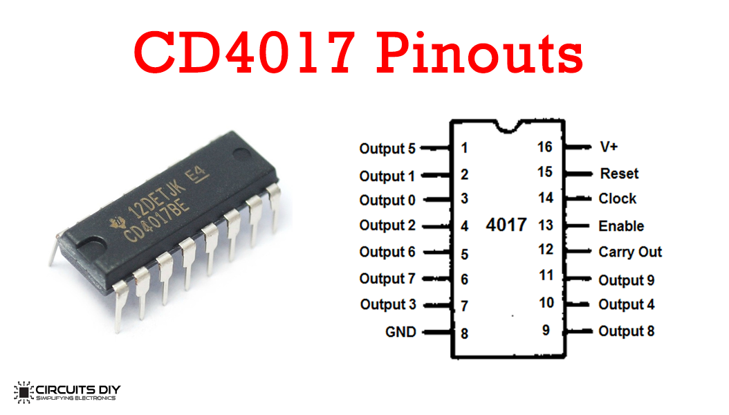
For a detailed description of pinout, dimension features, and specifications download the datasheet of CD4017
LM7805 Pinout
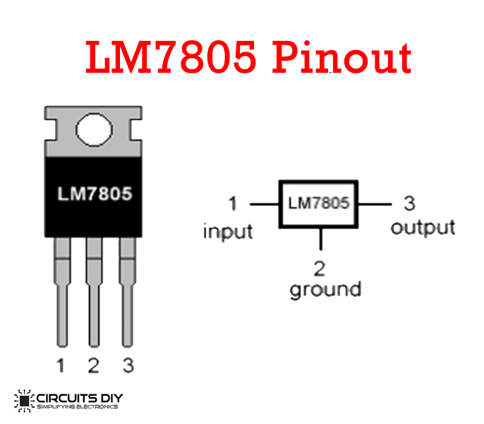
For a detailed description of pinout, dimension features, and specifications download the datasheet of LM7805
BC547 Pinout
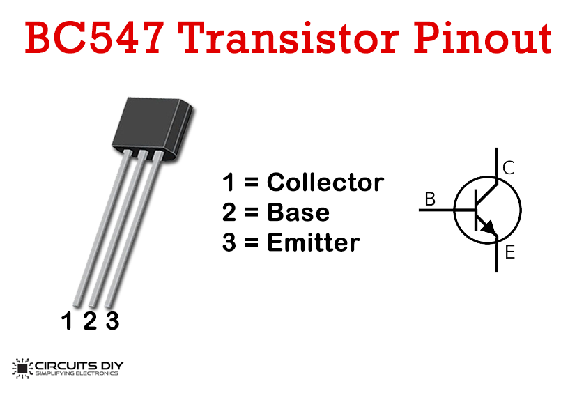
For a detailed description of pinout, dimension features, and specifications download the datasheet of BC547
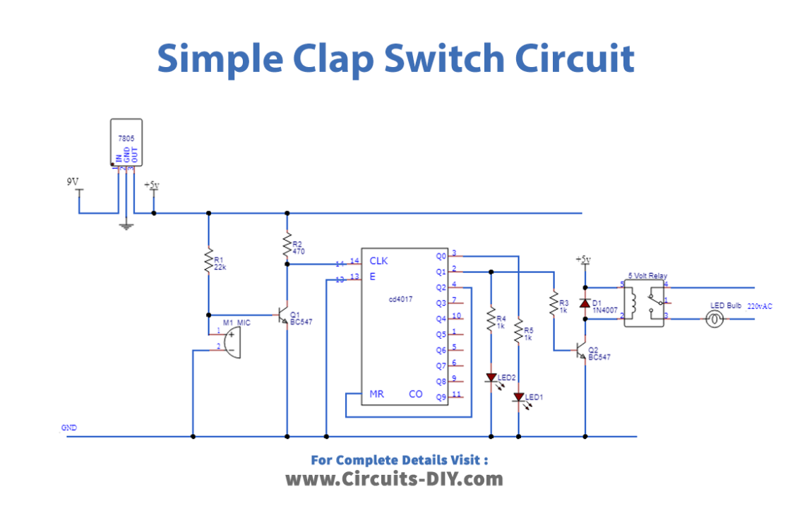
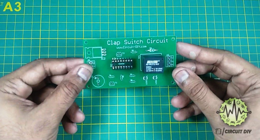
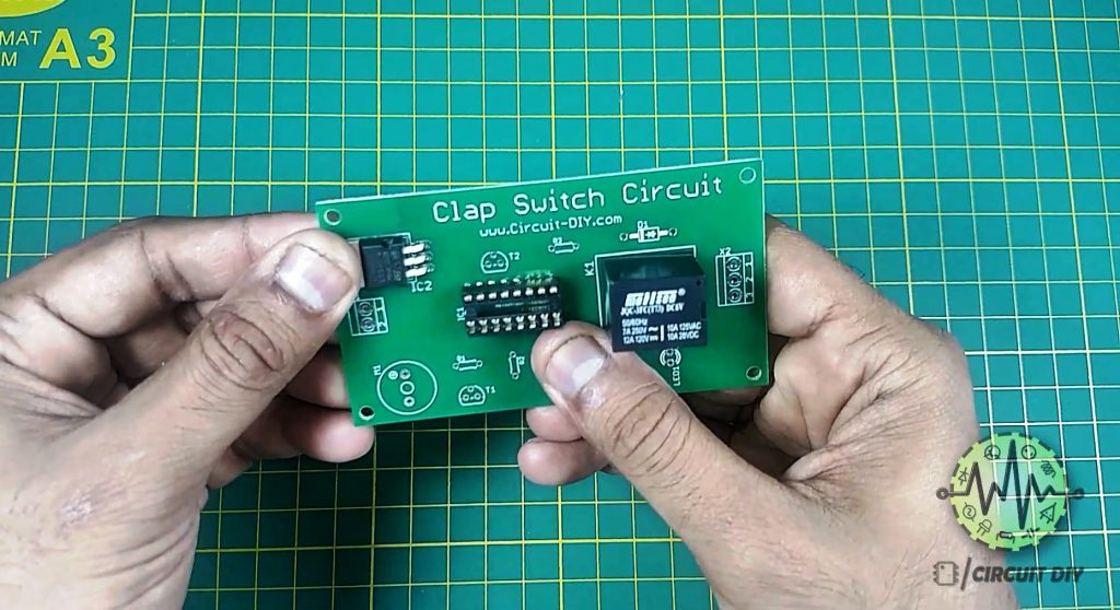
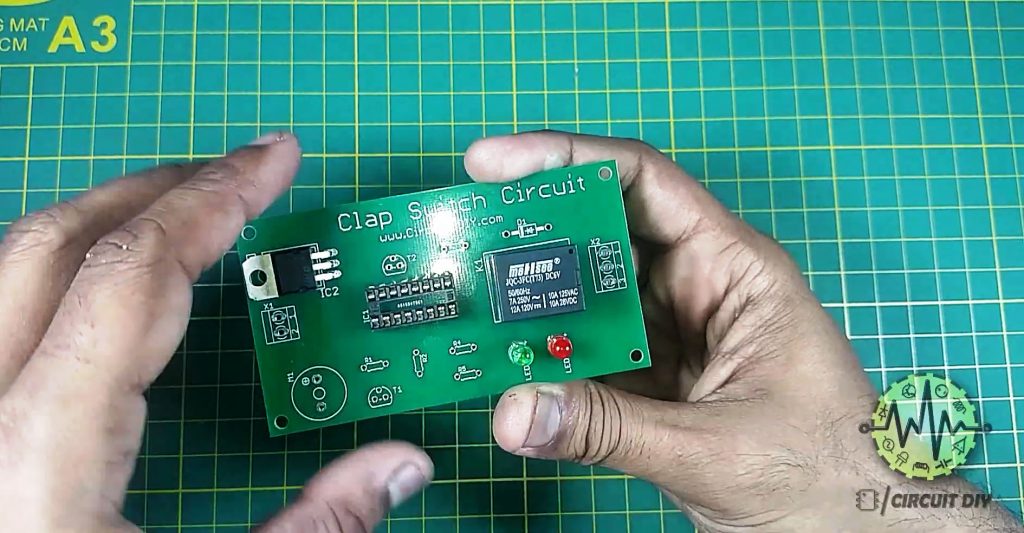
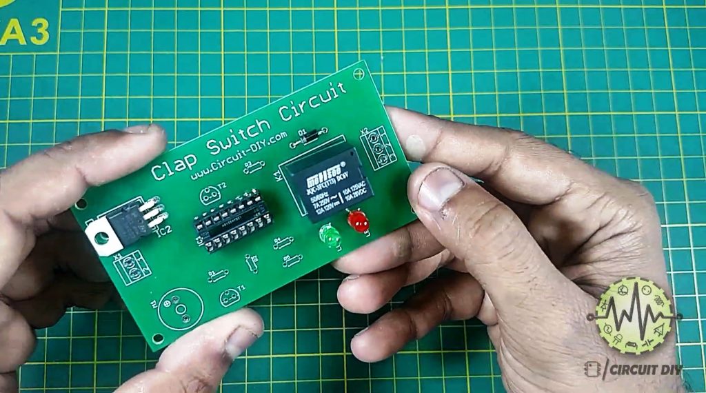
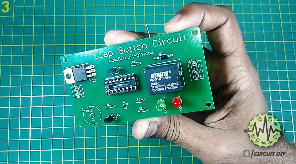
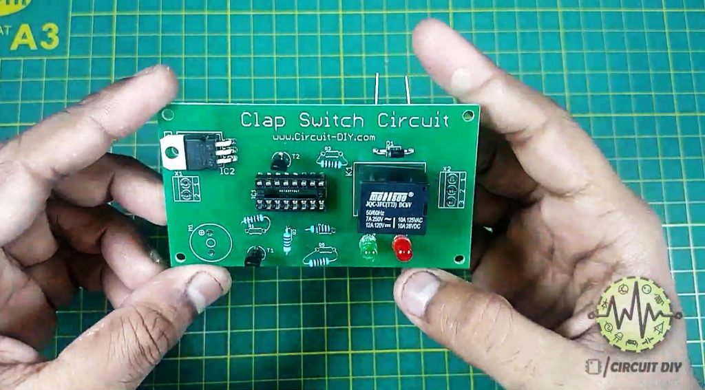
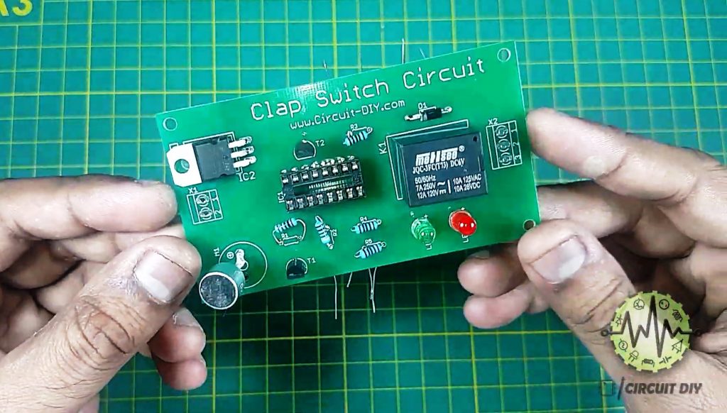
Clap Switch Circuit
Steps
1) Solder 5V SPDT Relay onto the PCB Board

2) Solder the IC Jacket for CD4017 on the PCB Board
3) Solder the LM7805 Regulator IC on the PCB Board
4) Solder the LEDs and the 1N4007 diode on the PCB Board
5) Solder BC547 Transistors onto the PCB Board
6) Solder Resistors (R1, R2, R3, R4, R5)
7) Solder the condenser mic on the PCB Board
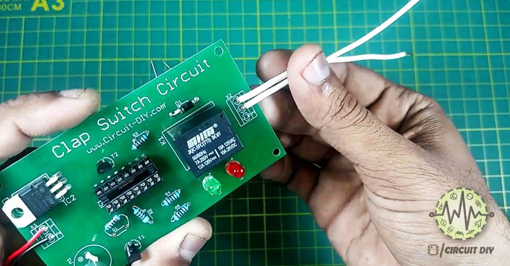
8) Solder Input (Battery Clips) & Output Connectors to the PCB Board
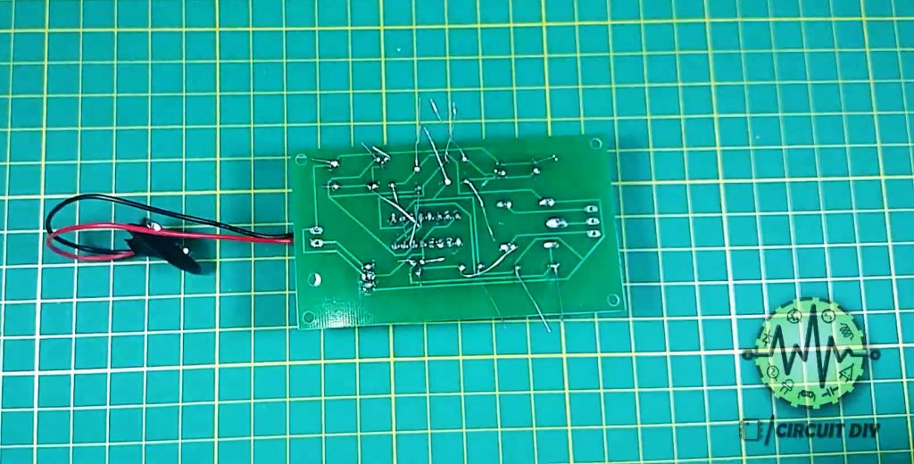
9) Trim any extra wiring

10) Connect the CD4107 IC & 9V battery, then power up the circuit
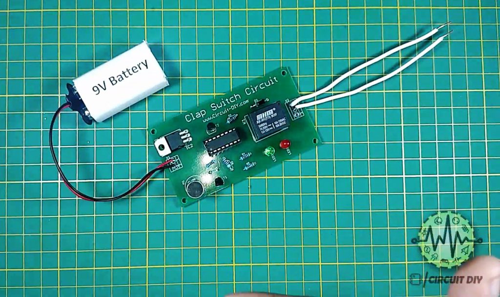
11) Test the circuit
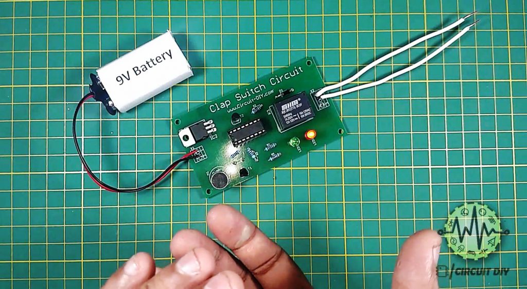
Working Explanation
The heart of this circuit is a CD4017 decade counter IC. An AC audio signal is received by an audio transducer such as a condenser mic. The AC signal from the mic serves as a control signal to the base of the BC547 transistor acting as a switch.
The collector output from the BC547 provides a clock input to Pin 14 of the counter IC, triggering Output pins Q0, Q1 & Q2 of the IC. The output from the IC acts as a control signal to the base of the second BC547 NPN transistor & triggers LEDs 1 & 2. The output from the transistor energizes the internal coil of the 5V SPDT relay. This makes the coil & completes the power circuit for an external output device such as a 220V Bulb. Here, we have used a diode (1N4007) to protect the SPDT relay from negative feedback in case of a short. Always use an SPDT relay with a voltage rating comparable to the input supply (12V/9V/5V).
Applications
- A sound switch circuit is not just for turning LEDs ON and OFF, but it can be in use in any electric appliance such as Tube Light, Fan, Radio, or any other basic circuit which you want to turn ON & OFF only by sound.
- Control AC Appliances by just clapping by hand.
- Security Alarm switches where its some time necessary to remote trigger the alarm.
Related posts:
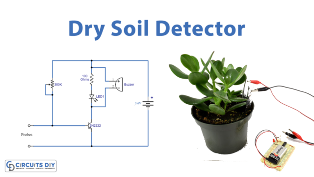 Plant Watering Watcher Or Dry Soil Detector
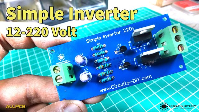 Easy Inverter Circuit with 2SC1815 Transistors
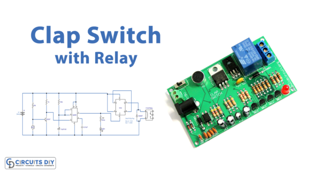 Clap Switch Circuit with Relay
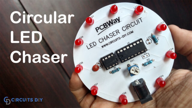 LED Chaser Circuit using 555 and 4017 | Dancing LED | DIY Electronics
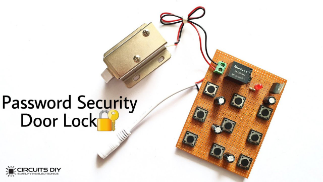 Password Security Door Lock Circuit by Using IRF540 MOSFET
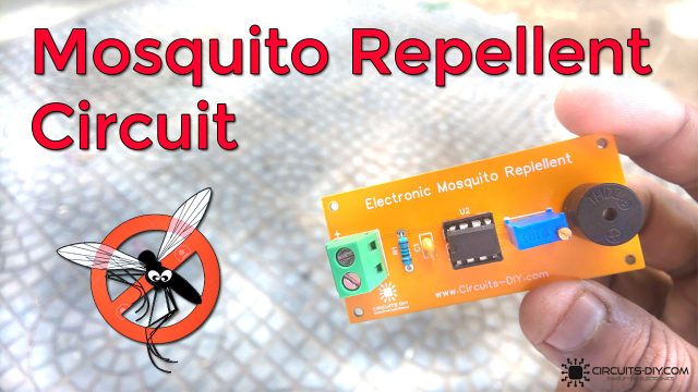 Simple Insect Mosquito Repellent - Electronics Projects


