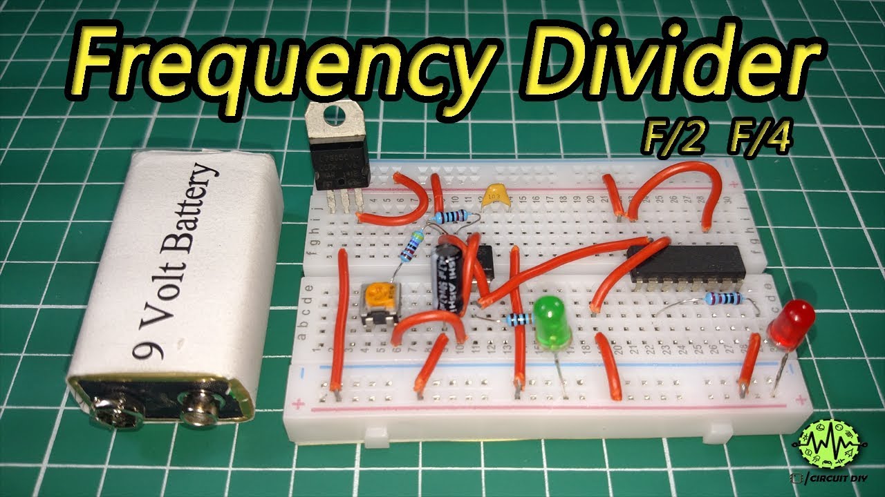
What are Frequency Dividers?
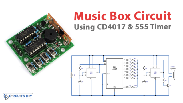
Frequency Divider Circuit is a circuit that divides the input frequency by n (any integer number), which means if we provide some signal of frequency ‘f’ then the output will be the divided frequency ‘f/n’. Frequency dividers are very useful in analog as well as digital applications. So in this tutorial, we are going to make “Frequency Divider using 555 Timer & CD4017 IC” which divides the frequency by 2 or 4.
The heart of this circuit is a NE555 Timer IC. The IC possesses an oscillation frequency ranging from 670 to 680 Hz. Here, this NE555 timer acts as an astable multivibrator. An astable multivibrator is a free-running oscillator that switches continuously between its two unstable states. With no external signal applied, the transistors alternately switch from cutoff to saturation state at a frequency that RC time constants of the coupling circuit determine. If these time constants are equal (R and C are equal) then a square wave will generate with a frequency of 1/1.4 RxC. Hence, an astable multivibrator is also a pulse generator or a square wave generator.
Hardware Components
| S.no | Component | Value | Qty |
| 1. | Breadboard | – | 1 |
| 2. | Battery | 9v | 1 |
| 3. | Connecting Wires | – | 1 |
| 4. | IC | NE555 Timer | 1 |
| 5. | Decade Counter IC | CD4017 | 1 |
| 6. | POT | 50K | 1 |
| 7. | Capacitors | 4.7uF,10nF | 1,1 |
| 8. | Slider Switch | – | 1 |
| 9. | LED | 5mm | 2 |
| 10. | IC Voltage Reg | LM7805 | 1 |
| 11. | Resistors | 330, 220, 10K, 47k ohm | 2, 2, 2, 2 |
555 Timer Pinout

CD4017 Pinout
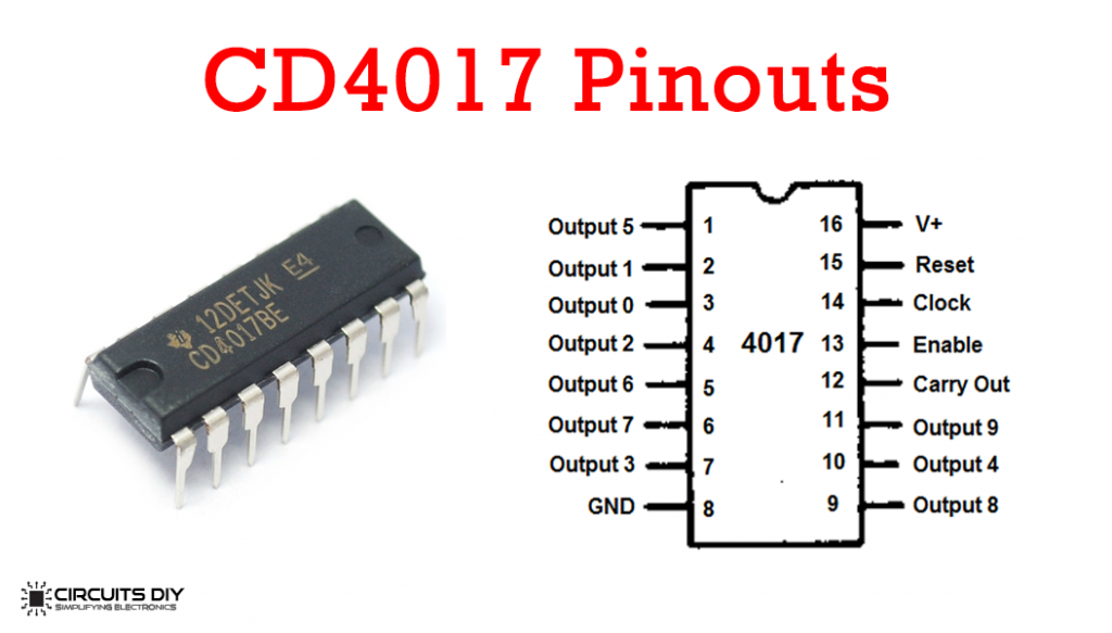
| Pin No. | Pin Name | Description |
| 1-7 & 9-11 | OUTPUT | pins to receive the output in a sequential manner. (Q0-Q9) |
| 8 | VSS | Ground Pin |
| 12 | CARRY OUT | To connect one or more CD4017 ICs. |
| 13 | CLK INHIBIT | It is used to switch the counter “on” and “off” |
| 14 | CLOCK | Whenever the CLK pin goes high, it provides the output. |
| 15 | RESET | It is used to reset the counter to zero. |
| 16 | VDD | Positive Voltage Supply pin to IC |
Frequency Divider Circuit

Working Explanation
Here we are using a 555 based astable multivibrator for the input signal and a potentiometer for controlling the signal frequency. On completing the circuit, the Astable Multivibrator generates a frequency which can be easily seen by the blinking LED. This signal is applied to the clock input of counter IC 4017 as a clock pulse.
If the frequency is to be divided by 2 (f/2), we apply the Q2 output to PIN 15 (RESET) of counter IC by using SPDT switch, so that the counter IC resets itself and starts from the beginning (Q0). Meaning, that for first clock pulse output Q1 will be high and for second clock pulse output, Q2 will be high which resets the IC and makes the output Q0 high. For third clock pulse output, Q1 will be high again and the LED will glow. So for every two input clock pulse, LED D2 will be high once.
Similarly, for the frequency to be divided by 4, we apply the Q4 output to Pin 15 of counter IC by using an SPDT switch. So that, IC 4017 will be reset in the fourth pulse, hence LED D2 will glow once during four pulses. Initially, Q0 will be high that is the default state of IC, then for first clock pulse output Q1 will be high and LED D2 will glow. For second and third clock pulses, output Q2 and Q3 will be high respectively. Now in fourth pulse Q4 gets high and resets the IC as it is connected to reset pin 15 of IC 4017 (Q0 high). For the fifth clock pulse output, Q1 will be high again and LED will glow. So, for every four input clock pulses, LED D2 will be high once, that how it divides the frequency by 4.
Applications
Frequency Divider Circuits are an integral part of many communication and audio based systems like:
- Frequency Synthesizers
- Audio Equipment
- Radar and Satellite Communication
- Military Equipment
- RF Devices