CD4516 Presettable Binary Up/Down counter consists of four synchronously clocked D-type flip-flops connected as counters. These counters can be cleared by a high level on the RESET line and can be preset to any binary number present on the jam inputs by a high level on the PE line. Synchronous cascading is accomplished by connecting all clock inputs in parallel and connecting the CARRY OUT of a less significant stage to the CARRY IN of a more significant stage.
The IC can be cascaded in the ripple mode by connecting the CARRY OUT to the clock of the next stage. If the UP/DOWN input changes during a terminal count, the CARRY OUT must be gated with the clock, and the UP/DOWN input must change while the clock is high. The IC is always available in 16 – pin hermetically sealed package and is directly interfaceable with every TTL, CMOS & NMOS device.
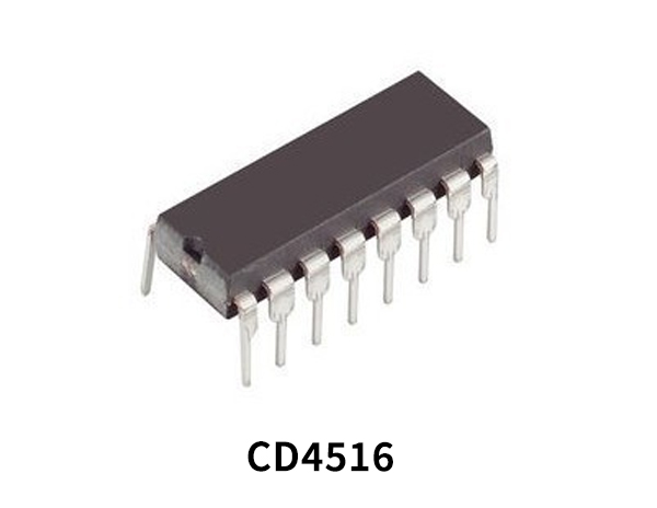
Binary Up/Down Counter
A binary up/down counter is a simple digital logic configuration that can count immediate as well as subsequent events in an increasing as well as decreasing order. For example a 4-bit binary up/down counter can count from 0000 to 1111 and also from 1111 to 0000. A simple Binary up/down counter can easily be made by rigging at least two D – type flip flops. A 4 bit binary counter will act as a decade counter by skipping any six outputs out of the 16 (24) outputs.
CD4516 Key Features
- High Voltage Types (20V Rating)
- CD4510BMS – BCD Type
- CD4516BMS – Binary Type
- Medium Speed Operation
- fCL = 8MHz Typ. at 10V
- Synchronous Internal Carry Propagation
- Reset and Preset Capability
- 100% Tested for Quiescent Current at 20V
- 5V, 10V and 15V Parametric Ratings
- Standardized Symmetrical Output Characteristics
- Maximum Input Current of 1µA at 18V Over Full Package Temperature Range; 100nA at 18V and +25oC
- Noise Margin (Over Full Package/Temperature Range)
- 1V at VDD = 5V
- 2V at VDD = 10V
- 2.5V at VDD = 15V
CD4516 Pinout
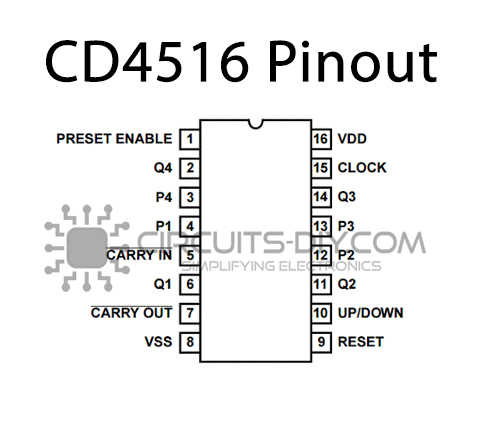
| Pin No | Pin Name | Description |
|---|---|---|
| 1 | PRESET ENABLE | PRESET ENABLE |
| 2 | Q4 | Output Pin 4 |
| 3 | P4 | Input Pin 4 |
| 4 | P1 | Input Pin 1 |
| 5 | CARRY IN’ | Invert of Carry Input |
| 6 | Q1 | Output Pin 1 |
| 7 | CARRY OUT’ | Invert of Carry Output |
| 8 | VSS | Source Supply |
| 9 | RESET | RESET |
| 10 | UP/DOWN | Set UP Or DOWN |
| 11 | Q2 | Output Pin 2 |
| 12 | P2 | Input Pin 2 |
| 13 | P3 | Input Pin 3 |
| 14 | Q3 | Output Pin 3 |
| 15 | CLOCK | Clock Signal Pin |
| 16 | VDD | Drain Supply |
Application
- Up/Down Difference Counting
- Multistage Synchronous Counting
- Multistage Ripple Counting
- Synchronous Frequency Dividers
CD4516 Datasheet
You can download the datasheet for CD4516 Binary Up/Down Counter from the link given below:
See Also: CD4584 Hex Schmitt Trigger – Datasheet | CD40110 Decade Up/Down Counter – Datasheet | CD4555 Dual Binary 1 of 4 Decoder – Datasheet




Comments are closed.