Astable Multivibrator circuit mode for 555 timer IC is also called Free running or self-triggering mode. It doesn’t have any stable state it has two quasi-stable states (HIGH & LOW). No external triggering is required in Astable mode, it automatically interchanges its two states on a particular interval, hence generating a rectangular waveform. So in this tutorial, we are going to make an “Astable Multivibrator using 555 Timer“. Watch the video for Step by Step instructions
An astable multivibrator is a free-running oscillator that switches continuously between its two unstable states. With no external signal applied, the transistors alternately switch from cutoff to saturation state at a frequency that RC time constants of the coupling circuit determine. If these time constants are equal (R and C are equal) then a square wave will generate with a frequency of 1/1.4 RxC. Hence, an astable multivibrator is also a pulse generator or a square wave generator.

Hardware Components
The following components are required to make Astable Multivibrator Circuit
| S.no | Component | Value | Qty |
|---|---|---|---|
| 1. | Breadboard | – | 1 |
| 2. | Battery | 9v | 1 |
| 3. | Connecting Wires | – | 1 |
| 4. | IC | NE555 Timer | 1 |
| 5. | Resistor | 220 Ohm, 1k, 100k | 1,1,1 |
| 6. | Capacitor | 10µF, 0.01µF | 1, 1 |
| 7. | LED | 5mm | 1 |
555 Timer Pinout
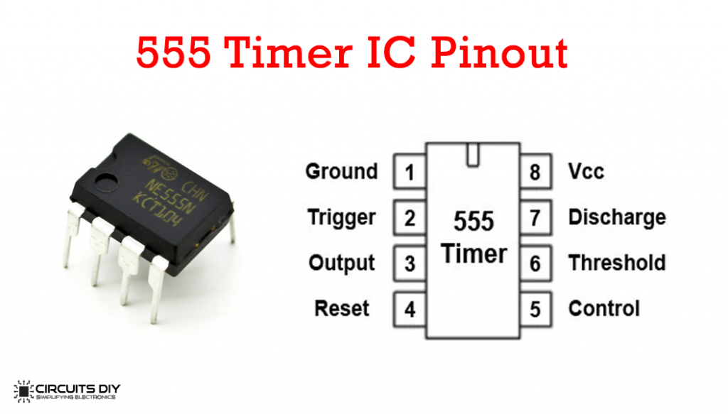
For a detailed description of pinout, dimension features, and specifications download the datasheet of 555 Timer
Astable Multivibrator Circuit

Working Explanation
In astable mode, the output PIN cycles from HIGH to LOW continuously, both the threshold pin and the trigger pin are connected to the 10uF capacitor. Therefore the voltage levels will be identical on the trigger pin, threshold pin, and the 10uF capacitor.
When the circuit receives power, the voltage is LOW at the capacitor, the threshold pin, and the trigger pin. Remember, if the trigger pin voltage is LOW, the output is HIGH. With the discharge pin in its off state, the current is able to flow through resistors which in turn charges our 10uF electrolytic capacitor.
When the capacitor’s charge reaches two-thirds of Vcc+, the output pin is deactivated. When the output pin is LOW, the discharge pin switches on causing the capacitor to drain to the ground. Once the capacitor voltage drops to one-third of Vcc+, the trigger pin disables the discharge pin and the capacitor starts charging again.
Application
- Astable multivibrators are used in radio gears to send or transmit radio signals such as RF signals.



Comments are closed.