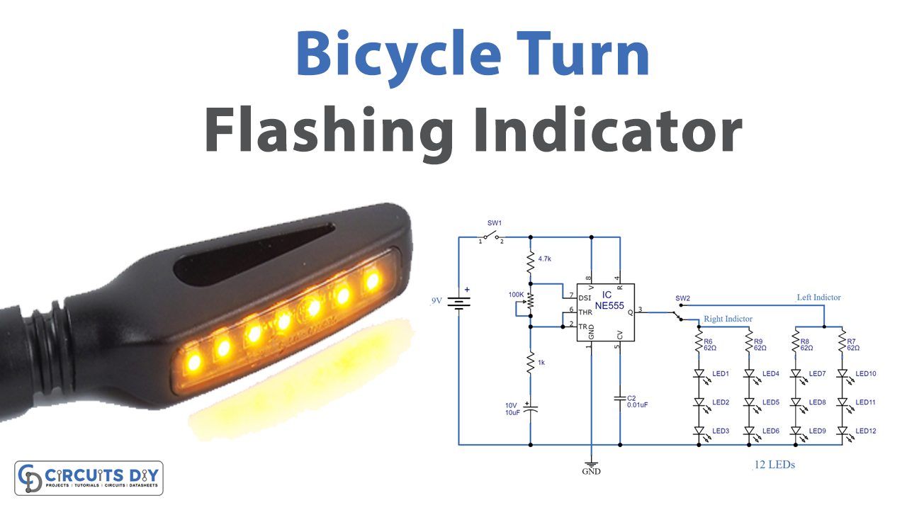
Bicycle turn flashing indicators, also known as directional indicators or Blinkers. Turn flashers are an important part of all automobiles whether a bike or a car. They inform other automobiles & pedestrians of our intent of turning left or right. There are several regulations & safety standards that manufacturers must follow while designing & integrating turn blinkers into a vehicle. In this project, we are going to design a simple bicycle turn flashing indicator using a NE555 timer IC
The objective of this circuit is to indicate a left or right turn for a vehicle. The main component of this circuit is a NE555 Timer IC. The IC possesses an oscillation frequency ranging from 670 to 680 Hz. Here, this NE555 timer acts as an astable multivibrator: It generates the pulse signal with variable width. Using this variable width of the pulse, we can set different time delays for the LEDs (ON and OFF for LEDs).
Hardware Component
You will need the following parts to build this project.
| S.no | Component | Value | Qty |
|---|---|---|---|
| 1. | Breadboard | – | 1 |
| 2. | Connecting Wires | – | 1 |
| 3. | Battery | 9v | 1 |
| 4. | IC | NE555 Timer | 1 |
| 5. | POT | 100K ohm | 1 |
| 6. | Resistor | 4.7k,1k,62 | 1,1,1 |
| 7. | Electrolytic Capacitor | 10uF,0.01uF | 1,1 |
| 8. | Slider Switch | – | 1 |
| 9. | LED | 5mm | 12 |
555 Timer Pinout

| Pin Number | Pin Name | Description |
| 1 | GND | Ground |
| 2 | TRIG | Trigger, set to 1/3 of Vcc |
| 3 | OUT | Timer Output |
| 4 | RESET | Reset active low |
| 5 | CONT | Comparator threshold control |
| 6 | THRES | Threshold, set to 2/3 of Vcc |
| 7 | DISCH | The low-impedance discharge path |
| 8 | Vcc | Chip supply voltages (6v-12v) |
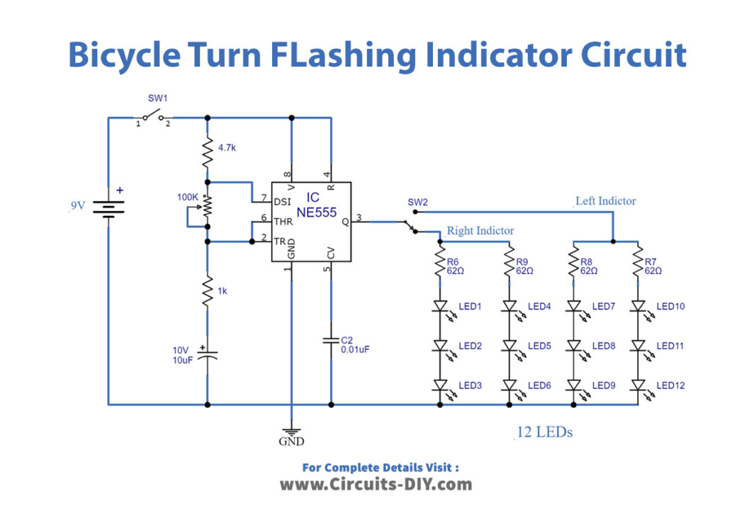
Circuit Diagram
Working Explanation
The heart of this circuit is a NE555 precision timer IC, providing the clock for the flashing of the LEDs. In this circuit, the 555 timer IC produces a pulsating signal with variable width, through variations in resistance or capacitance values (4.7 KΩ, 1KΩ, or 10µF). TRIG & THRES pins are shorted together to allow triggering after every timing cycle. The blinking speed of the LEDs can be adjusted with the 100KΩ variable resistor.
The fourth pin is reset, it is shorted with a VCC pin to avoid sudden resets. The 7th pin is discharging pin, it is connected to the Threshold pin through a 1KΩ resistor. The circuit is operated in the following manner:
- Initially connect a 9V power supply to the circuit.
- Keep the SPDT slider switch in the center position.
- Slide the switch to the Left position and you can observe that the LEFT Indicator LED set will start to Blink with some delay.
- If you slide the switch to the Right Position, the RIGHT Indicator LED will start Blinking.
- If you slide the switch to the center, both the LED set will switch OFF
Applications
- Commonly used in vehicles such as cars, bikes, bicycles & buses.
- Used in high-priority indication signs such as roadwork signs, hazardous area indications & speed limit indicator signs.