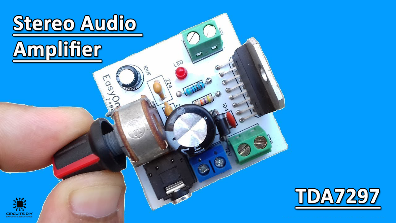
What is a Stereo Audio Amplifier Circuit?
A Stereo Audio amplifier is a simple electronic circuit that boosts a low power AC audio signal to a level where it is strong enough to be driven by an audio transducer such as a headphone or loudspeaker. Audio amplifiers have proven their worth in today’s electronics, whether it be a simple toy or a complex music production process. So, in Today’s tutorial, we will go through a step by step process on how to design a Stereo Audio Amplifier Circuit Using TDA7297 Dual Bridge Amplifier IC.
The heart of this circuit is a TDA7297 amplifier IC. TDA7297 IC is a Stereo dual bridge, Class AB dual channel audio amplifier. It is available in a compact 15-pin IC package and can operate with 6V to 18V making it suitable for consumer electronics like TV, Radio, Home theater, etc. TDA7297 IC can deliver up to 30W (15+15) of output power, so you can run two 4Ω speakers at 15W each for stereo audio quality.
JLCPCB is the foremost PCB prototype & manufacturing company in china, providing us with the best service we have ever experienced regarding (Quality, Price Service & Time).
Hardware Components
You will need the following parts to build this project:
| S.no | Component | Value | Qty |
|---|---|---|---|
| 1. | Amplifier IC | TDA7297 | 1 |
| 2. | Loudspeaker | 15W, 4 Ohms | 2 |
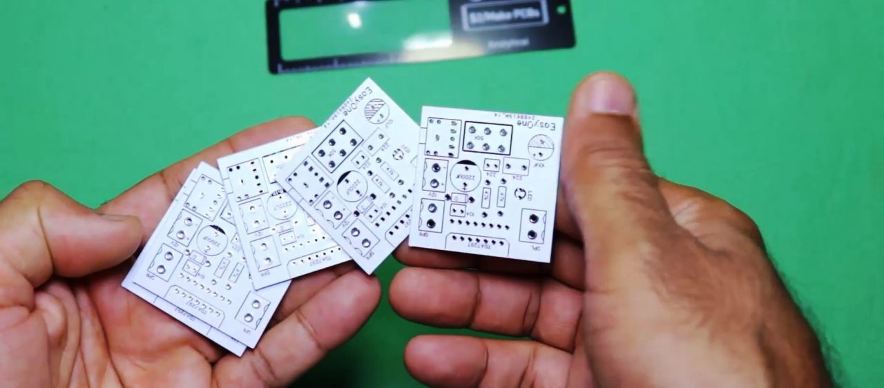
| 3. | Stereo Audio Amplifier PCB | AllPCB | 1 |
| 4. | Audio jack | 3.5mm, Male & female | 1 |
| 5. | LED | 5mm, 3.5V | 1 |
| 6. | Diode | RL207 | 1 |
| 7. | Capacitor | 2200uF, 10uF, 220nF, 100nF | 5 |
| 8. | Potentiometer | 50K | 1 |
| 9. | Resistor | 4.7K | 1 |
| 10. | Soldering Iron | 45W – 65W | 1 |
| 11. | Soldering Wire with Flux | – | 1 |
| 12. | DC Battery | 12V | 1 |
| 13. | Battery Clips | – | 1 |
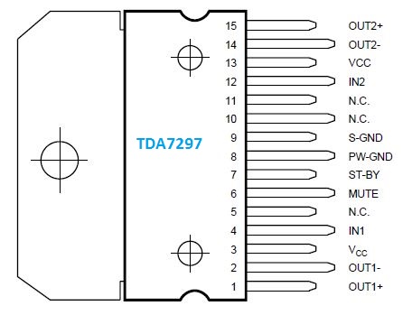
TDA7297 Pinout
| Pin Name | Pin No. | Description |
|---|---|---|
| OUT1+ | 1 | Channel 1- Non-Inverting Output |
| OUT1- | 2 | Channel 1 – Inverting Output |
| Vcc | 3 | Chip supply voltage (6V to 18V) |
| IN1 | 4 | Channel 1 Input |
| NC | 5 | No Connection |
| MUTE | 6 | Used to mute the output |
| STAND-BY | 7 | Puts the IC on stand-by when not used to save battery charge |
| PW-GND | 8 | Ground terminal of power supply |
| S-GND | 9 | Ground terminal of audio (signal) |
| NC | 10 | No Connection |
| NC | 11 | No Connection |
| IN2 | 12 | Channel 2 Input |
| VCC | 13 | Chip supply voltage (6V to 18V) |
| OUT2- | 14 | Channel 2 – Inverting Output |
| OUT2+ | 15 | Channel 2- Non-Inverting Output |
Useful Steps
1) Design the PCB using a PCB layout tool such as EasyEDA. After that order the PCB using an online PCB fabrication service such as AllPCB. To learn more about how you can order your first PCB using AllPCB design services please visit their website by clicking here.
2) Solder all the components on the PCB board.
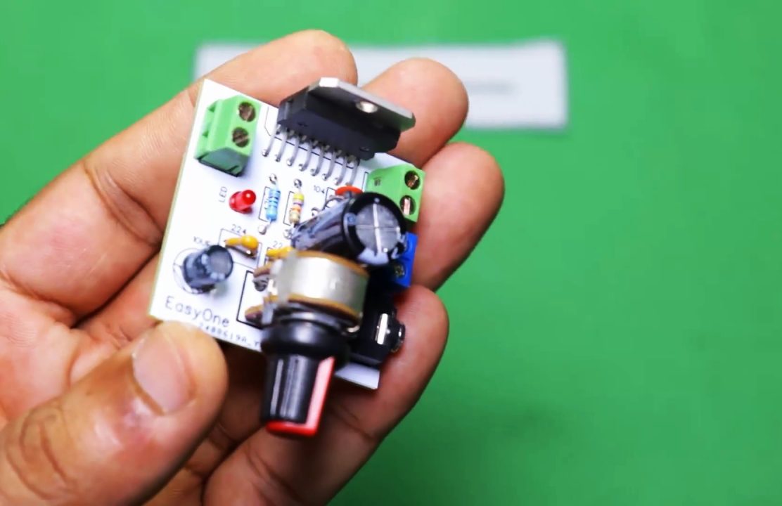
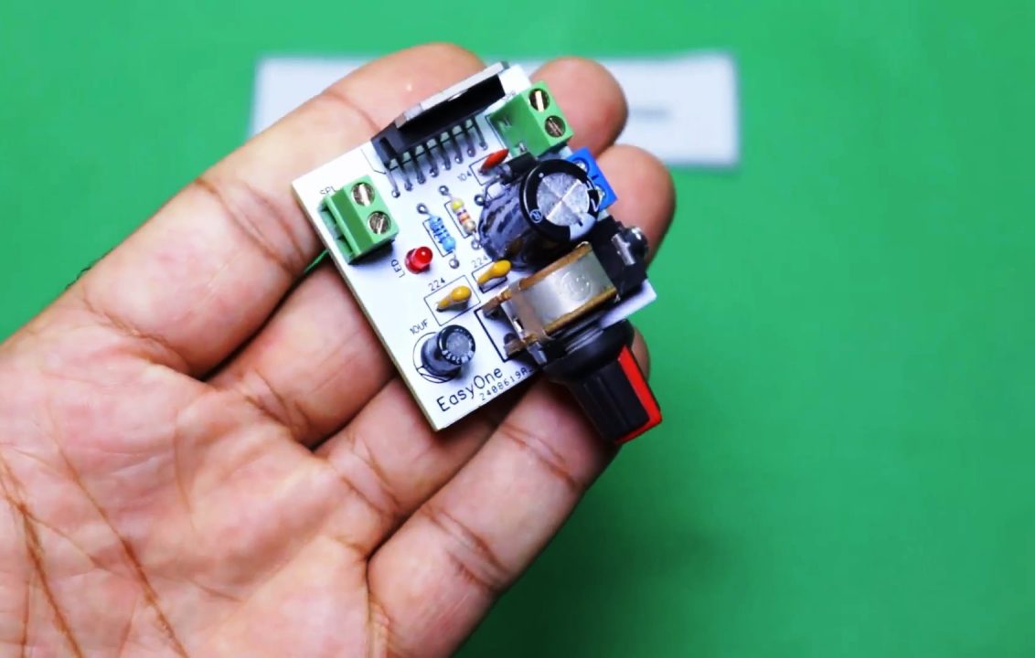
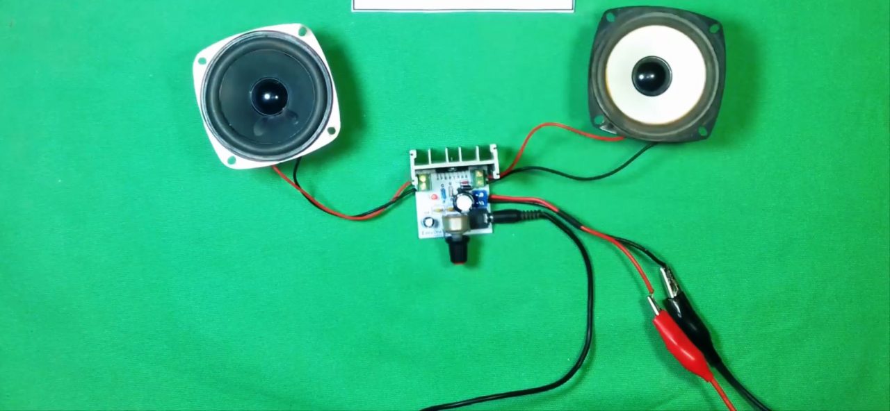
3) Connect the +ve & -ve terminals of the two 4 Ohm loudspeakers with the amplifier output through block connectors . You can also solder a heat sink with the PCB board to reduce temprature.
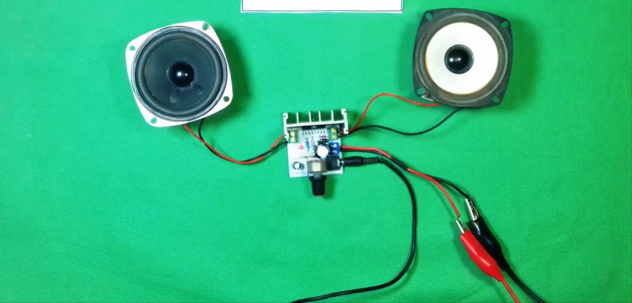
3) Connect the 3.5mm audio jack to an audio source (smartphone). After that, power up & test the circuit.
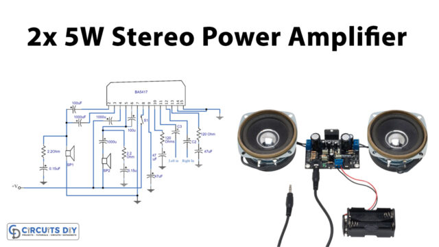
Circuit Diagram For Stereo Audio Amplifier
Working Explanation
This circuit can take dual audio input & can project the output on two separate 15W 4 Ohm speakers. The working of this circuit is as follows, Audio input from a device such as a smartphone is taken at the inverting inputs (pin 4 & 12) of the TDA7297 IC. Here, two 220nF coupling capacitor is used to block the DC component of the signal allowing only the AC component to pass through.
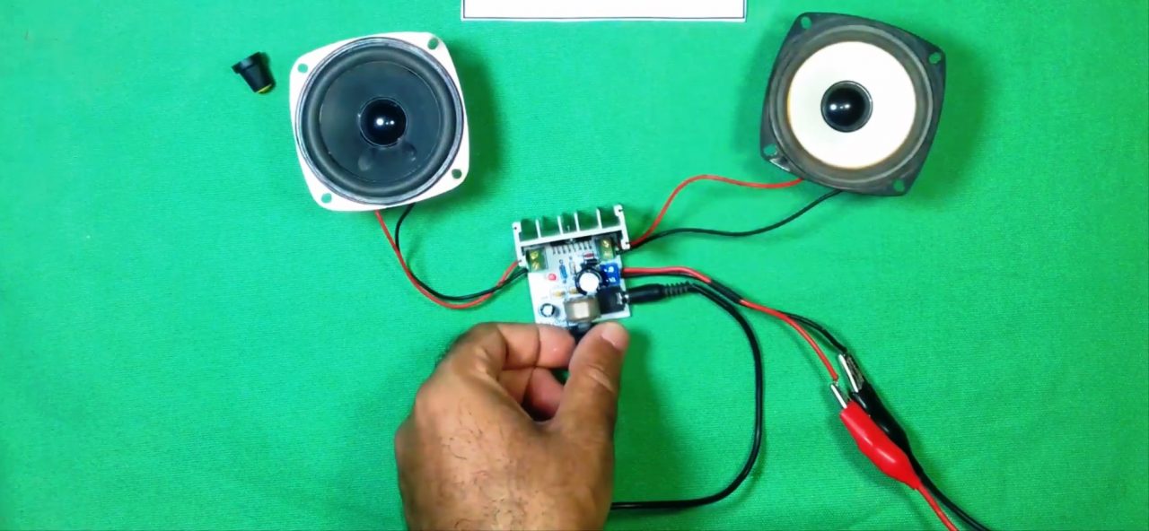
The circuit allows you to adjust the intensity of the output sound by adjusting the MUTE & ST-BY pin using a 10uF & 50K pot RC combination. The 15W 4 ohm speakers can be connected to the two outputs provided on the IC. You can use a 12V battery to operate this circuit smoothly.
Applications
- Usually used in small toys, media players & small electronic projects.
- Also widely used in the entertainment industry for live music production & recording.
Gerber File
You can download the gerber file for the above schematic from the link given below: