A headphone amplifier is a relatively low-power amplifier that boosts the low-voltage audio signal from a source device (be it a turntable, laptop, or smartphone) to a sufficient level, such that it converts (or transduces) into sound waves by the speakers inside your headphones. It works like the amps which power full-sized speakers but also operate at a lower scale. In this project, we are going to build a simple headphone amplifier circuit using some transistors.
A Headphone amplifier circuit is integral when it comes to mass media production & recording. They are small, easy to use and design & provide low power consumption.
Hardware Components
The following components are required to make Headphone Amplifier Circuit
| S.No | Component | Value | Qty |
|---|---|---|---|
| 1. | Breadboard | – | 1 |
| 2. | Battery | 9v | 1 |
| 3. | Ceramic Capacitor | 1uF | 1 |
| 4. | Resistors | 100K, 68K, 10K, 4.7K, 3.3K, 2.2K, 1.5K, 330Ω | 1, 1, 1, 1, 1, 1 1, 1 |
| 5. | Polar Capacitors | 470μF, 100μF | 1, 1 |
| 6. | NPN transistor | BC237 | 2 |
| 7. | Mic | – | 1 |
| 8. | Audio Jack | – | 1 |
BC237 Pinout
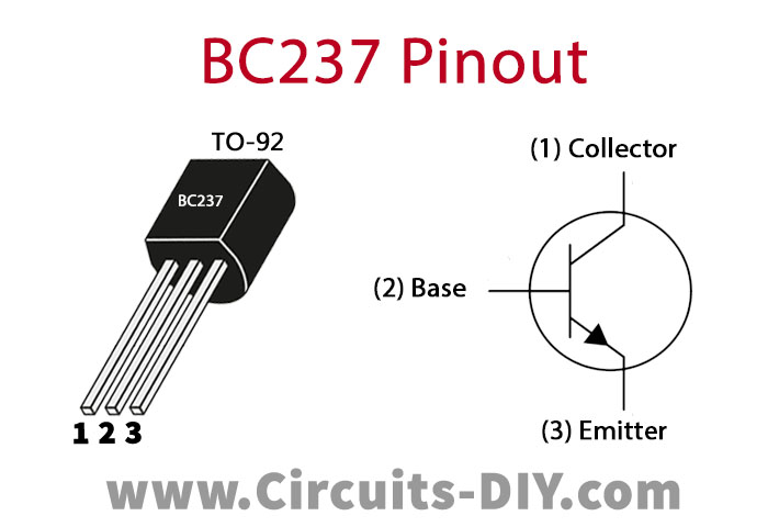
For a detailed description of pinout, dimension features, and specifications download the datasheet of BC237
BC239 Pinout
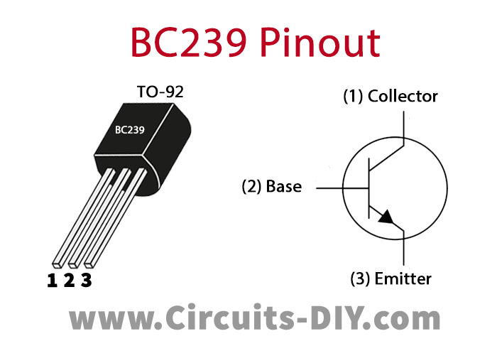
For a detailed description of pinout, dimension features, and specifications download the datasheet of BC239
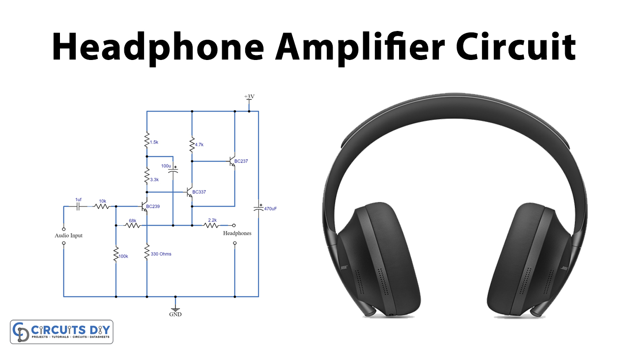
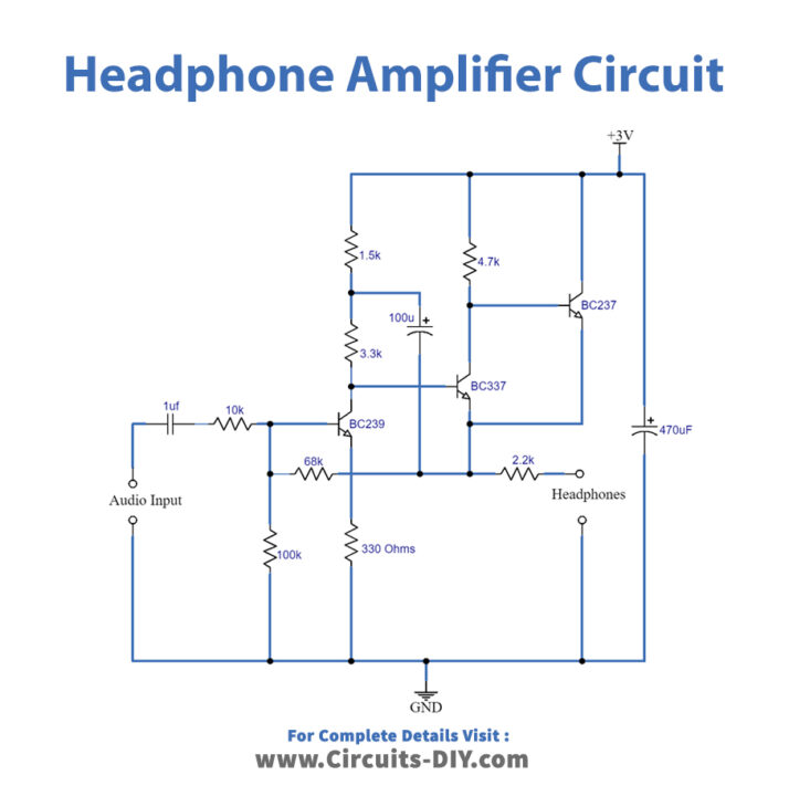
Headphone Amplifier Circuit
Working Explanation
This circuit operates in two stages: preamplification & amplification. The input comes through a PC, Laptop, or smartphone and the output delivers to a headphone via a female jack port. The capacitor (1μF) blocks the DC component, allowing the AC component to pass through and reach the preamplification stage.
Transistor Q1(BC239C) preamplifiers the incoming audio, Transistor Q1 is set up as a collector-base biasing function, by connecting a 68KΩ resistance. This resistor offers negative feedback for the transistor Q1. The output of Q1 reaches the base of Q2, serving as an input control signal. After pre-amplification, the audio signal is now further amplified by Q2 (BC337) & Q3 (BC237) before being sent to the output speakers (Headphones). This circuit should be operated by a 3V-5V supply voltage.
Applications
- Generally used to drive & improve the sound quality of headphones with relatively low impedance.
- Also used as an output stage for preamplifiers coupled with active loudspeakers.
- Also used for amplifying subwoofer or speaker output.