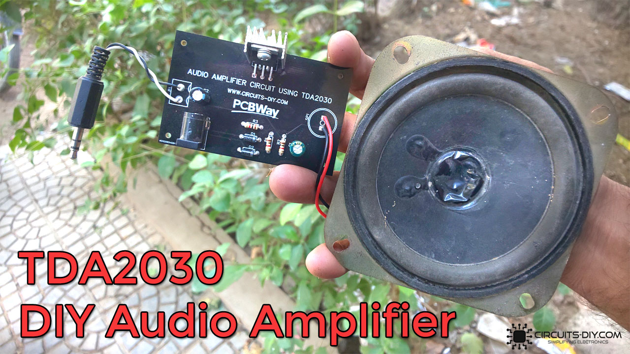
Would you like to know how to make an audio amplifier circuit? Audio Amplifiers are an essential part of modern electronics. Basically, it boosts the power of an audio signal by increasing the amplitude of a small sound signal to a useful level, all the while maintaining the smaller signal’s parameters. They are one of the most common in-use circuits when it comes to electronics and perform a wide variety of functions, So, in this project, we will understand how to make An Audio Amplifier circuit using TDA2030 Amplifier IC.
The heart of this circuit is a TDA2030 IC. The TDA2030 is a monolithic Hi-Fi Audio Amplifier IC. Typically, it provides 14 W output. The TDA2030 provides high output current and has very low harmonic and crossover distortion. Furthermore, the device incorporates a short circuit protection system. It also features ESD protection and thermal overload protection.
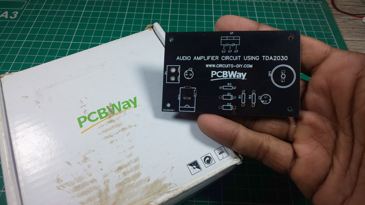
PCBWay commits to meeting the needs of its customers from different industries in terms of quality, delivery, cost-effectiveness, and any other demanding requests. As one of the most experienced PCB manufacturers in China. They pride themselves to be your best business partners as well as good friends in every aspect of your PCB needs.
Hardware Component
The following components are required to make Audio Amplifier Circuit
| S.no | Component | Value | Qty |
|---|---|---|---|
| 1. | Audio Amplifier IC | TDA2030 | 1 |
| 2. | Heatsink | – | 1 |
| 3. | Loudspeaker | 1W | 1 |
| 4. | DC Audio Jack | Female/Male 3.5mm | 1 |
| 5. | Diode | 1N4007 | 2 |
| 6. | Capacitor | 100uF, 47uF | 3 |
| 7. | Resistor | 1K | 1 |
| 8. | Soldering Iron | 45W – 65W | 1 |
| 9. | Soldering Wire with Flux | — | 1 |
| 10. | DC Power Jack | 12V | 1 |
| 11. | DC Battery | 12V | 1 |
| 12. | Battery Clip | – | 1 |
| 13. | Jumper Wires | – | As per need |
TDA2030 Pinout
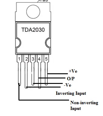
For a detailed description of pinout, dimension features, and specifications download the datasheet of TDA2030
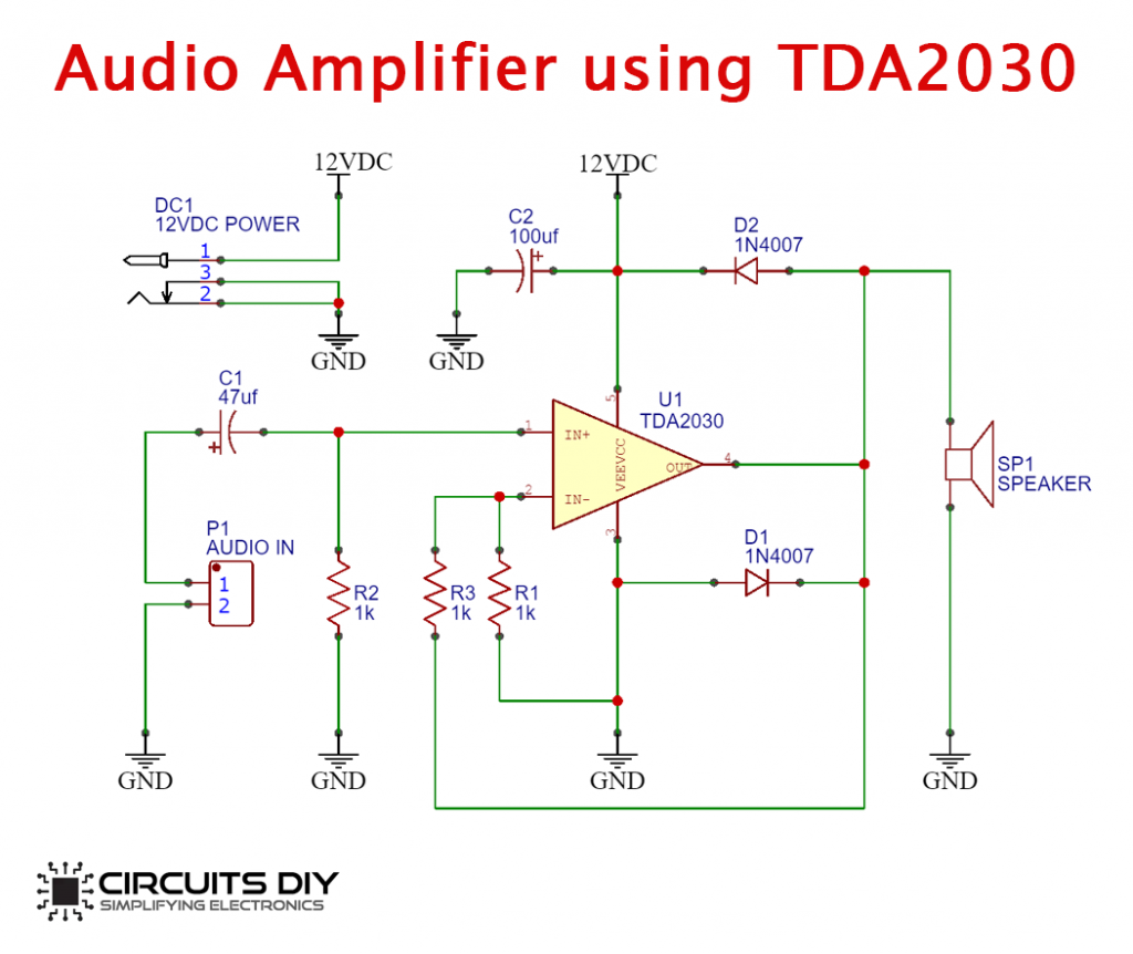
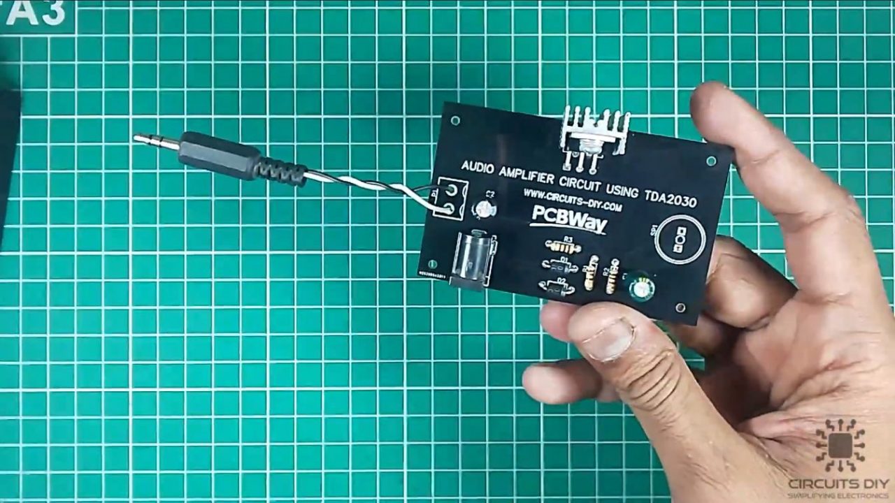
Audio Amplifier Circuit
Useful Steps
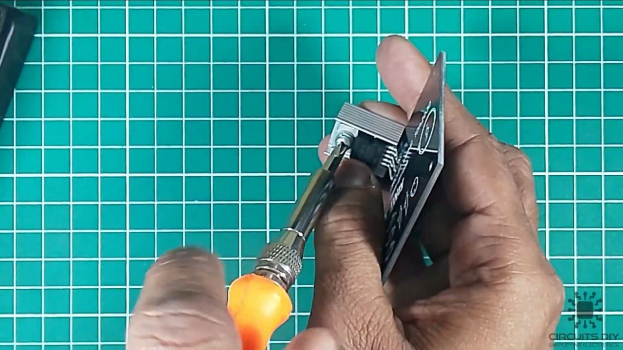
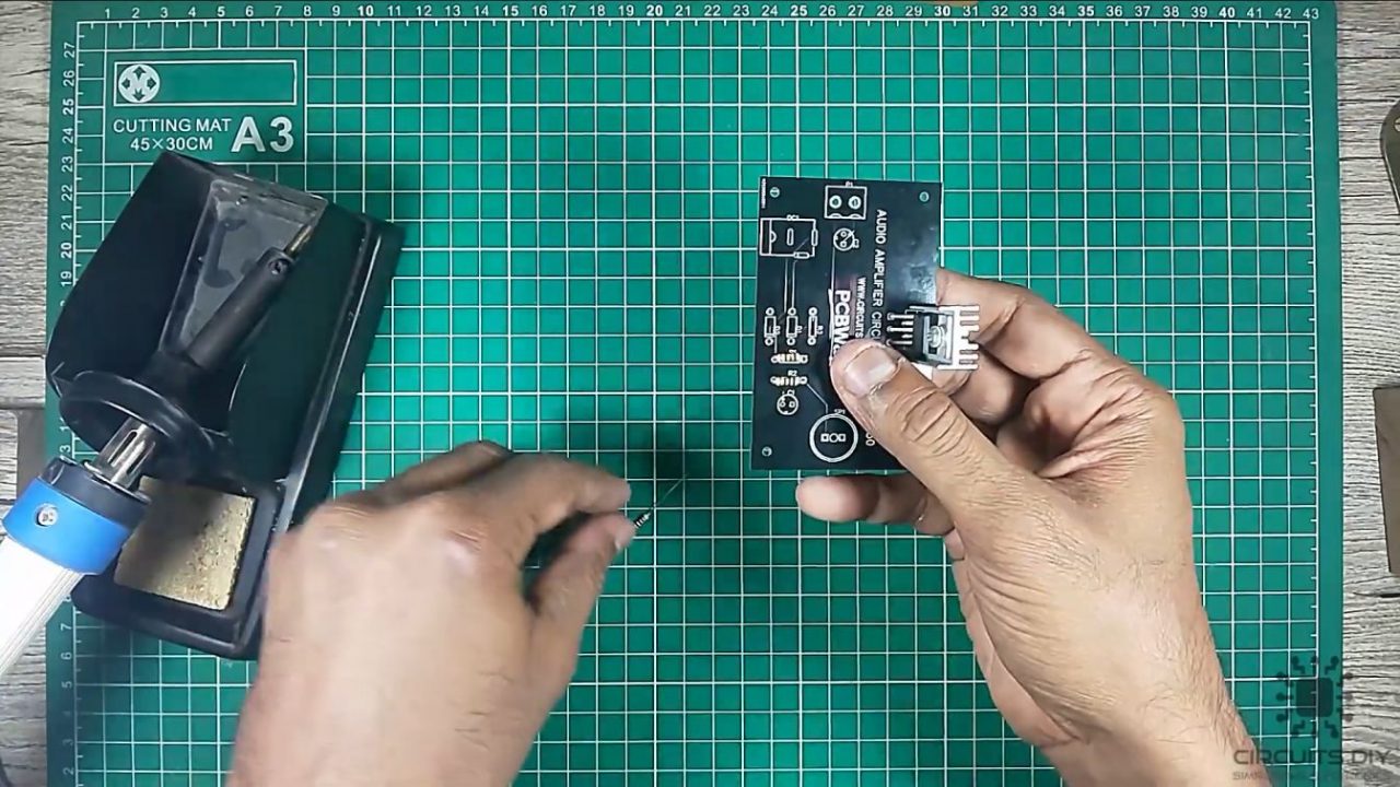
1) Solder the TDA2030 IC on the PCB board.
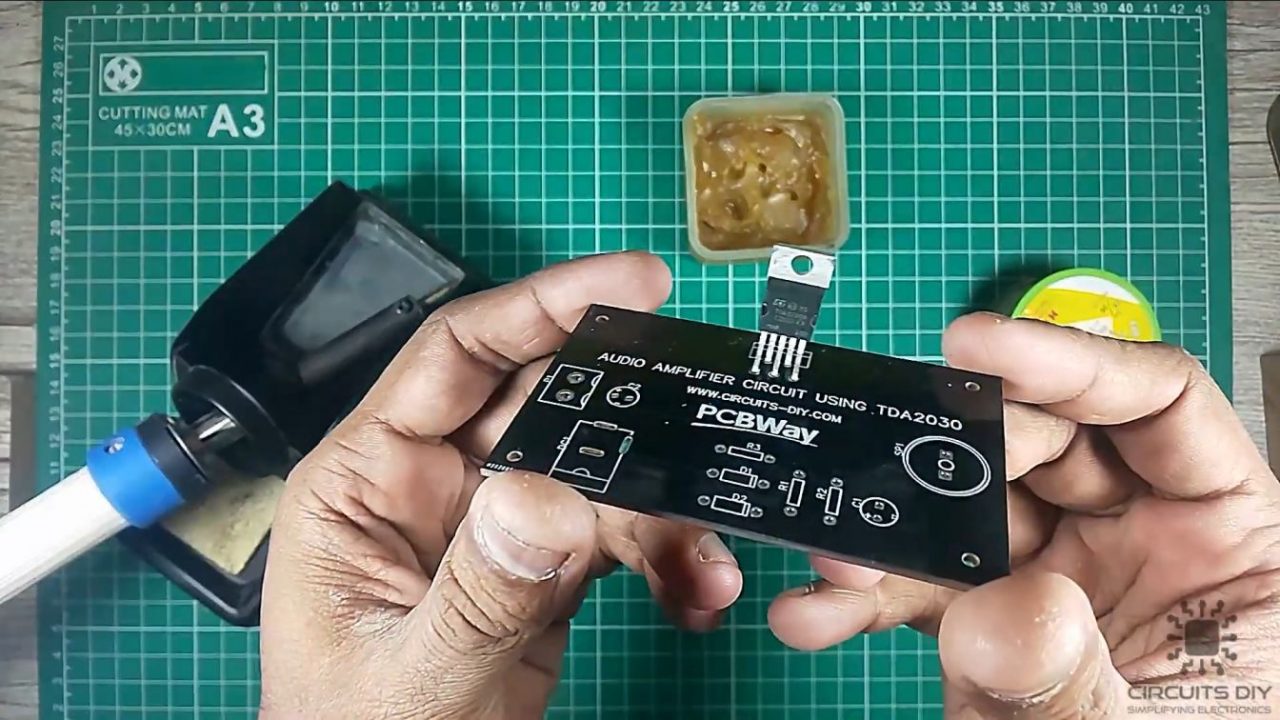
2) Connect the heatsink with the IC.
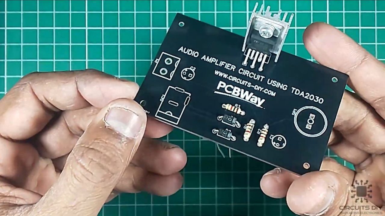
3) Solder the 1K resistors on the Veroboard.
4) After that, solder the two 1N4007 diodes on the PCB board.
5) Solder the 100uF and 47uF capacitors on the PCB board.
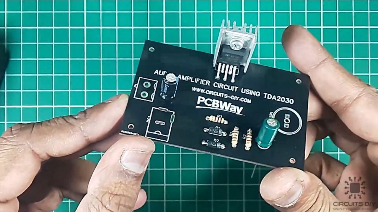
6) Solder the DC power jack on the PCB board.
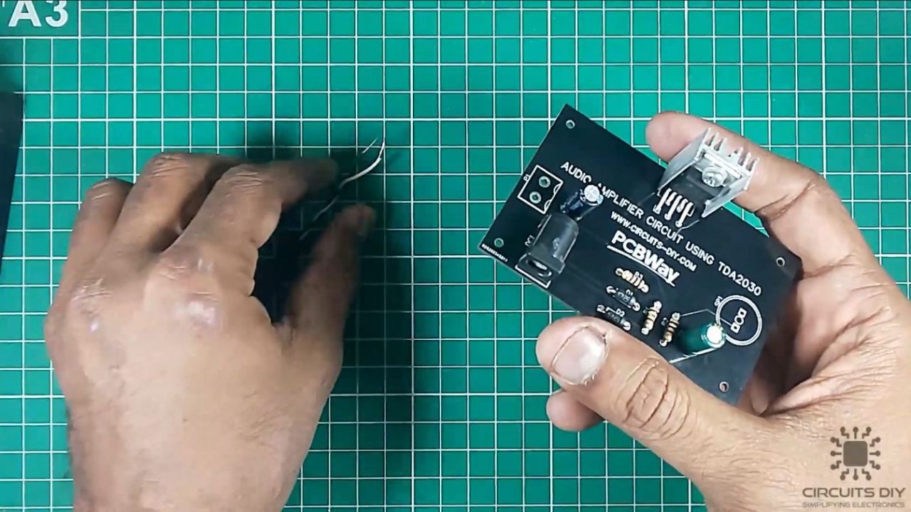
7) After that, solder the 3.5mm DC audio jack on the PCB board.
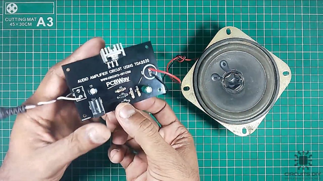
8) Solder the +ve and -ve pin of the 1W loudspeaker with the PCB board.
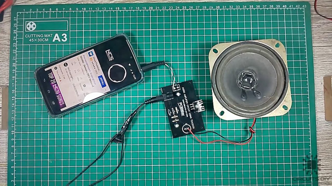
9) Power up and test the circuit.
Working Explanation
The working of this circuit is actually pretty simple. Audio input is taken from a device such as a smartphone or a mic. The audio input then goes through a coupling capacitor of 47uF. By using a coupling capacitor we are basically blocking the DC component of the input signal, allowing only AC to pass through. The capacitor output then goes to the non-inverting input pin of the IC.
The amplified output from the amplifier is then fed to an audio transducer such as a loudspeaker. Here, we are using two flyback diodes to protect the amplifier from any -ve feedback. You can use a 6V – 12V battery to run this circuit.
Applications
- Audio amplifiers generally serve in devices such as speakers, mics, dictaphones & a wide variety of other devices.
- they are important in the music production & recording process.
- they’re a common part of home entertainment devices such as mono & stereo speakers for home theatre setups.