
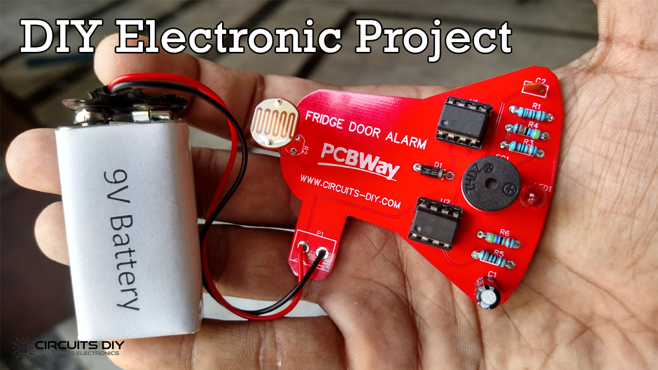
A fridge door alarm circuit using 555 timers senses the status of a fridge door being open OR close. It beeps if the fridge door is left open for too long or hasn’t been closed properly, in order to stop food from spoiling. There are lots of other implied uses to this circuit as well. A refrigerator or freezer door that is left open or ajar may cause the food contents to spoil. So today in this tutorial, I am going to show how to make a simple fridge door alarm circuit using 555 timer ICs.
The central part of this circuit is are NE555 Timer ICs. The IC possesses an oscillation frequency ranging from 670 to 680 Hz. Here, this NE555 timer acts as an astable multivibrator An astable multivibrator is a free-running oscillator that switches continuously between its two unstable states. With no external signal applied, the transistors alternately switch from cutoff to saturation state at a frequency that RC time constants of the coupling circuit determine. If these time constants are equal (R and C are equal) then a square wave will generate with a frequency of 1/1.4 RxC. Hence, an astable multivibrator is also a pulse generator or a square wave generator.
PCBWay commits to meeting the needs of its customers from different industries in terms of quality, delivery, cost-effectiveness, and any other demanding requests. As one of the most experienced PCB manufacturers in China. They pride themselves to be your best business partners as well as good friends in every aspect of your PCB needs.
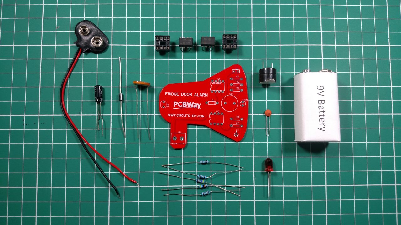
Hardware Components
The following components are required to make Fridge Door Alarm Circuit
| S.no | Components | Value | Qty |
|---|---|---|---|
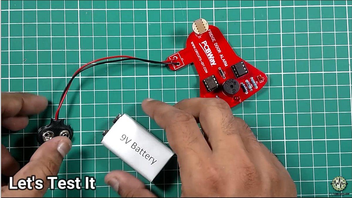
| 1. | Input Supply DC | 9-12V | 1 |
| 2. | Jumper Wire | – | 1 |
| 3. | IC | NE555 Timer | 2 |
| 4. | Buzzer | – | 1 |
| 5. | Diode | 1N4007 | 1 |
| 6. | LDR | LDR07 | 1 |
| 7. | Polar Capacitor | 47uF | 1 |
| 8. | Non Polar Capacitor | 0.1uF | 1 |
| 9. | LED | RED | 1 |
| 10. | Resistor | 100, 10k, 100K, 470k Ω | 1, 1, 1, 2 |
555 Timer Pinout

For a detailed description of pinout, dimension features, and specifications download the datasheet of 555 Timer
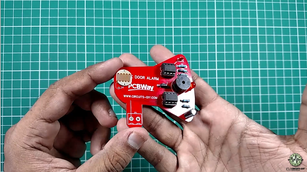
Fridge Door Alarm Circuit
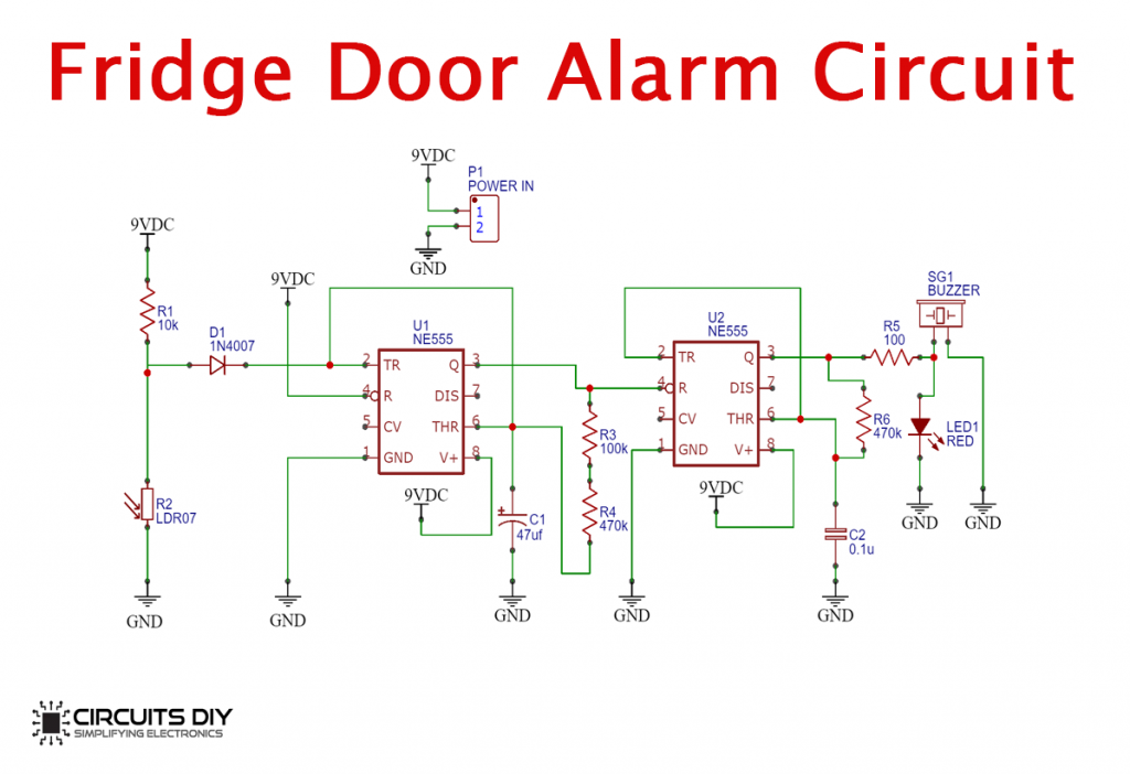
Working Explanation
When the fridge door is closed, the resistance of the LDR is almost 1MὨ. The output voltage of the potential divider appears across the capacitor and it remains in charged condition (Voltage greater than 2/3Vcc) making the output LOW. When the Fridge door is open, the light falls over LDR which lowers down the resistance of LDR and causes the capacitor to discharge. After this (Voltage lower than 2/3Vcc), the output starts to oscillate at a certain frequency and the output is HIGH. Again, the capacitor charges and reaches a threshold continued by the discharge of the capacitor. This continues till the LDR resistance goes high which happens in the absence of light.
Now, the second NE555 timer IC starts to oscillate and the output switches between HIGH & LOW causing the connected buzzer & LED to beep & blink in a fluctuating pattern respectively, which is combinational because of the oscillations of the first timer and the second timer internal oscillation. During the HIGH condition of the first timer output, the second timer RESET will trigger. Thus, the capacitor C2 charges (Voltage higher than 2/3Vcc), and output go LOW. In a short time span, the capacitor starts to discharge (Voltage lower than 2/3Vcc) causing the output HIGH. Hence, the buzzer connected to the output generates a beeping sound.
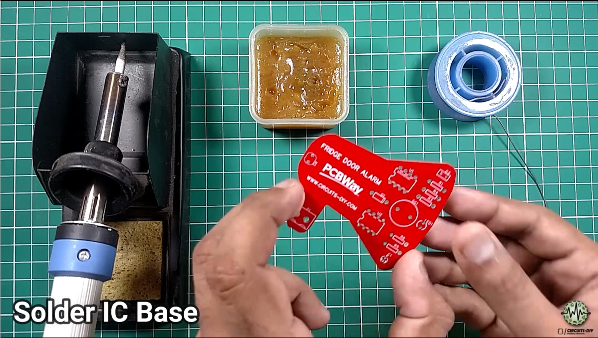
Steps
1) Solder Base of Both IC’s 555 Timer
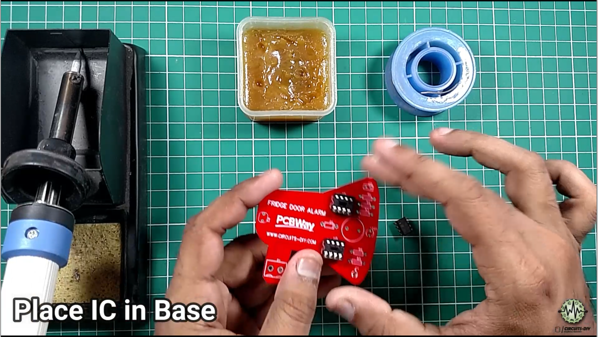
2) Place IC In Base
3) Solder All Resistors

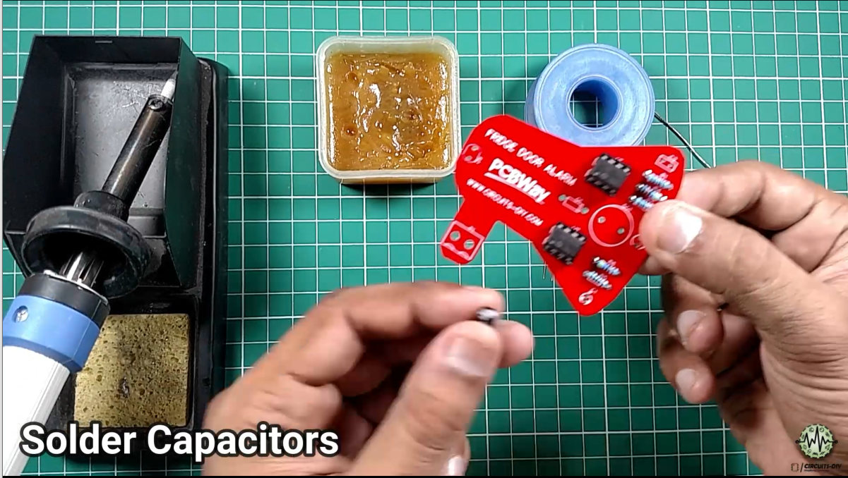
4) Solder Capacitors (Ceramic & Electrolytic)
5) Solder Diode & LED
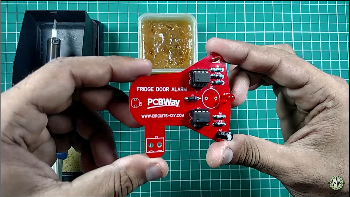
6) Solder LDR & Buzzer
7) Finally Solder Power Connector
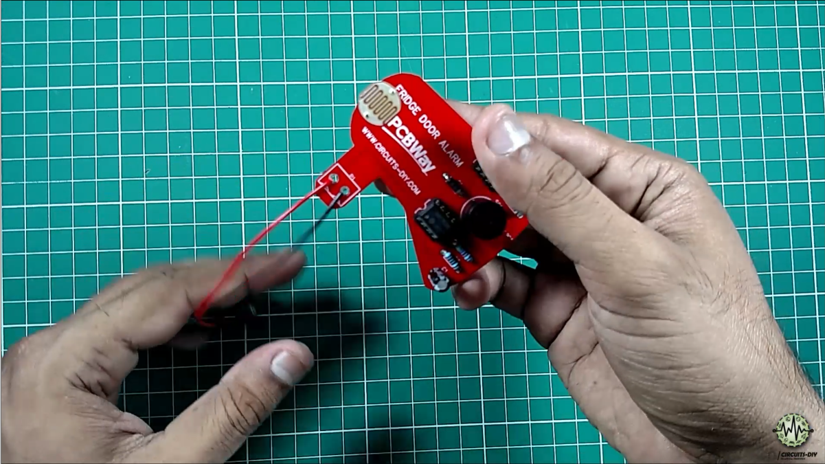
8) Let’s Power up the Circuit
Applications
- Commonly used in appliances such as refrigerators, Temperature Controlled Freezers & beverage coolers to ensure that the appliance is not left open for too long by accident.
Related posts:
 How To Make A Fogger/Mist Maker Circuit at Home
 How to Make Clap Switch | DIY Project | Home Automation | Electronics Projects
 LED Sequencer / Chaser Using 555 & 4017 ICs
 Sequential Sound Activated Switches - Electronics Project
 Bird Sound Generator Using 555 Timer IC
 Sound Activated Adjustable Battery Supply Using ICM7555 Timer


