Introduction
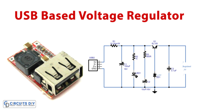
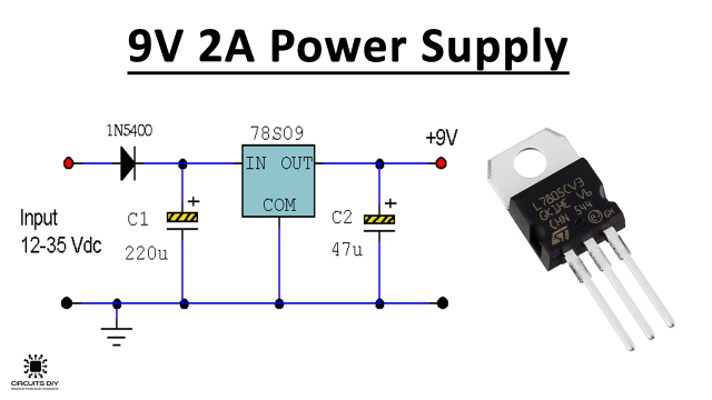
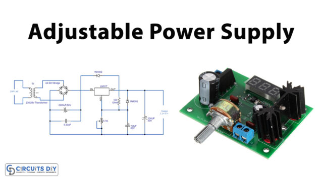
To maintain the voltage within the prescribed range, many circuits use voltage regulators. This small circuit helps to provide the fixed output voltage regardless of the change in input voltage. And, therefore, voltage regulator circuits are employed for many devices. From power supply to television and other electronic types of equipment, they have their usage everywhere. Hence, there are many different types of voltage regulators exist. In this tutorial, we are going to “Zener Diode Voltage Regulator Circuit”
Why Zener Diode?
At this point, your mind might arise the question that why we are not using a simple diode and adopting a Zener diode. The normal diode works in the forward direction and greater current flows on it with almost negligible voltage drop. So when that diode works in reverse biased, it generates an insignificant current, and thus it might destroy the diode. On the other side, the Zener diode operates better in reverse biased without damaging itself.
Hardware Components
The following components are required to make Zener Diode Voltage Regulator Circuit
| S.no | Component | Value | Qty |
|---|---|---|---|
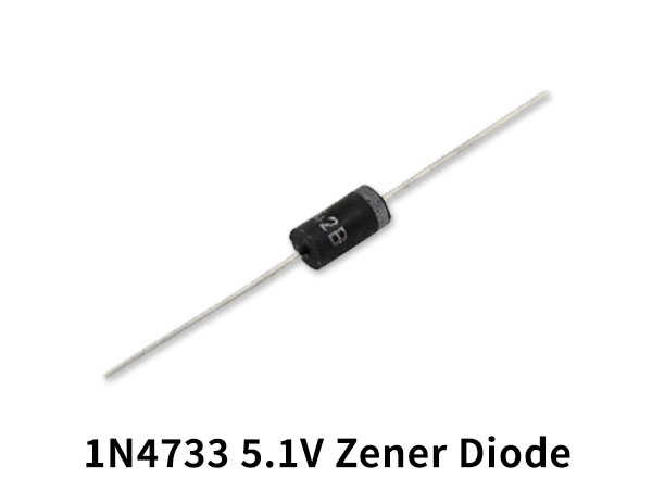
| 1. | Zener Diode | 5.1v | 1 |
| 2. | Resistor | 33-Ohm | 1 |
| 3. | Battery | 9V | 1 |
| 4. | 2 Pin Connector | – | 1 |
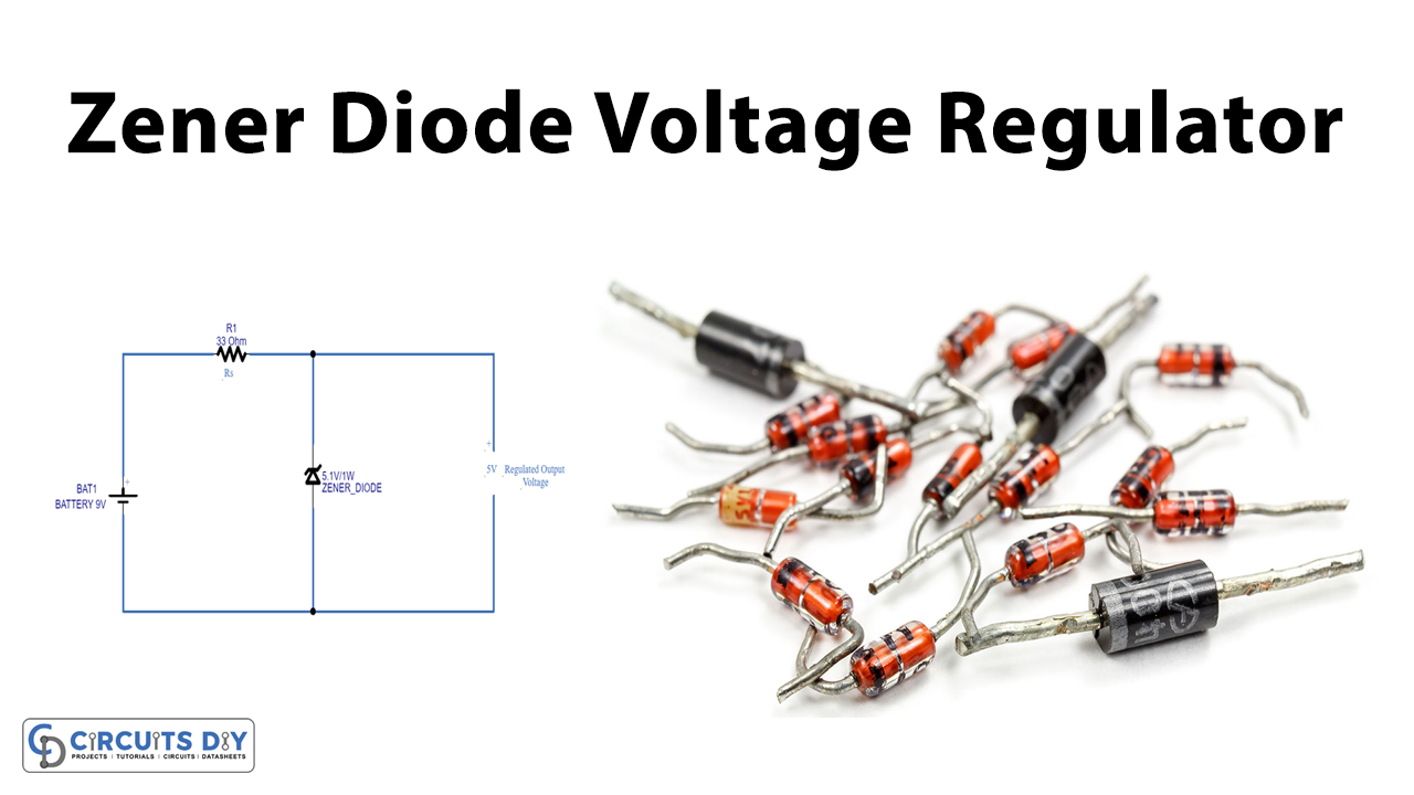
Zener Diode Voltage Regulator Circuit
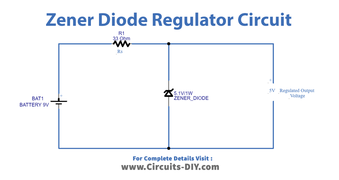
Working Explanation
In this Zener Diode Voltage Regulator Circuit, the Zener diode is the major component that we are using as a Regulator. In this circuit, we need to connect resistor Rs according to the the specifications of Zener diode and output voltage. Here we have used a Zener diode of 5.1V and wired 33ohms of resistance. When the input voltage increases more than the Zener breakdown voltage, the Zener diode conduct voltage up to the breakdown voltage level. as a result, provides regulated output voltage.
Application and Uses
- Power supply circuits need this circuit.
- Television, computers, laptops, etc
- Combustion engines
- Hence every device that needs regulated voltage


