In this tutorial, we are making a project on the wireless temperature sensor circuit. It is a very interesting and useful project for detecting the temperature of any remote place. You can easily detect the level of temperature or heat from a distance place.
This circuit is divided into three stages. The first stage is a temperature sensor circuit. The second stage has UM66 IC which is a CMOS melody generator. And the final stage is an FM transmitter circuit where the output is being transmitted.

Hardware Components
The following components are required to make Wireless Temperature Sensor Circuit
| S.no | Components | Value | Qty |
|---|---|---|---|
| 1. | Battery | 3V | 1 |
| 2. | Resistor | 1K, 39K, 100Ω | 2, 1, 1 |
| 3. | Ceramic Capacitor | 0.1µF, 1N, 28pF, 2pF, 10nF, 62pF, 5pF | 1, 1, 1, 1, 1, 1, 1 |
| 4. | Trimmer Capacitor | 1-30pF | 2 |
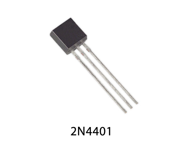
| 5. | Transistor | 2N4401, 2N3904 | 2, 1 |
| 6. | IC | UM66 | 1 |
| 7. | Thermistor | 10K NTC | 1 |
| 8. | Antenna | 12-30 inch | 1 |
| 9. | Coil L1 | 2 turns of # 24 enameled wire wound on 5mm form | 1 |
| 10. | Potentiomter | 200K | 1 |
| 11. | Variable Resistor | 10K | 1 |
2N4401 Pinout

For a detailed description of pinout, dimension features, and specifications download the datasheet of 2N4401
UM66 Pinout

For a detailed description of pinout, dimension features, and specifications download the datasheet of UM66
Wireless Temperature Sensor Circuit

Working Explanation
The first stage of this circuit which is a temperature sensor circuit is built around two 2N4401 transistors which are working as switches. A 10K thermistor is used to sense the heat. To adjust the level of heat on which you want the circuit to activate we have used a variable resistor of 20K. So, when the thermistor receives heat or temperature of the preset level it activates the transistors. The transistors will now switch on the whole process and send an input signal to the second stage where UM66 IC is placed. The IC will generate a melody this melody will be passed from the third stage i.e., the FM transmitter circuit. It will broadcast the melody signal to an FM receiver at a distance of 50 meters.
A 10K variable resistor is used to control the volume of the melody broadcasting. The oscillator stage of this circuit is built with the transistor 2N3904.
Circuit Adjustments: To make the circuit ready to perform adjust the 200K variable resistor on the place where it will activate the circuit at room temperature. When the circuit is activated and melody is broadcasting then switch ON the FM receiver and set it on a blank spot after 100 MHz and place it 5-10 m away from the transmitter. Adjust the trimmer of the transmitter until you hear a melody on FM radio. Your circuit will be ready to use once you hear the signal on your FM radio. Adjust the 200K VR again on your desired level of heat for using the circuit.


