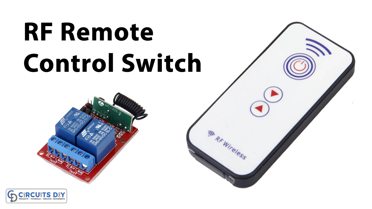
In this tutorial, we are demonstrating a project of Wireless RF Remote Control ON/OFF Switch which is a radio-controlled switch. Radio-controlled switches are exceptionally common these days. Unlike an infrared controlled switch, an RF (Radio Frequency) switch additionally works if there are any kind of barriers between, accordingly you can control your home appliances over the wall or in another room. For instance, you can switch your fan, lights, or other electronic apparatuses to another room while sitting on your bed.
Hardware Components
The following components are required to make RF Remote Control Circuit
| S.no | Components | Value | Qty |
|---|---|---|---|
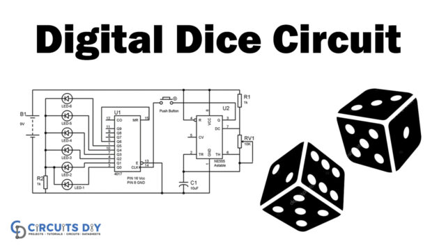
| 1 | IC | CD4017 | 1 |
| 2 | IC | LM358 | 2 |
| 3 | Battery | 5 – 12V | 1 |
| 4 | Diode | 1N34 | 1 |
| 5 | Diode | 1N4007 | 1 |
| 6 | Antenna | 80cm | 1 |
| 7 | LED | – | 2 |
| 8 | Relay | 5V | 1 |
| 9 | Coil | 6 turns | 1 |
| 10 | Variable Capacitor | 1-35pF | 1 |
| 11 | Resistor | 1K, 100KR, 10K, 120R, 100Ω, 390Ω | 2, 1, 1, 1, 1, 1 |
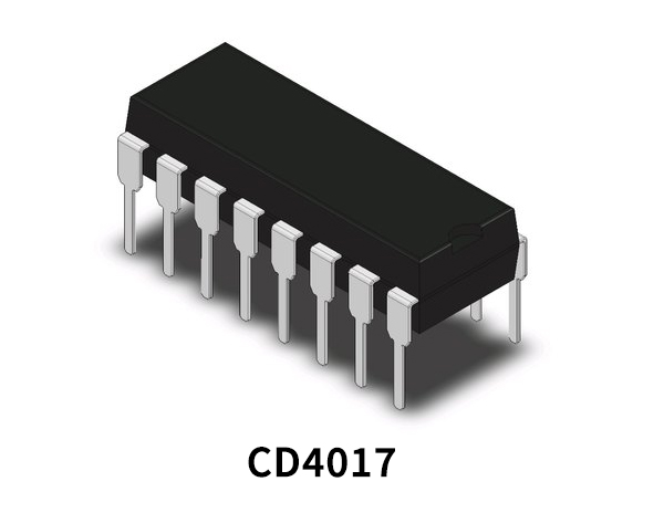
CD4017 Pinout
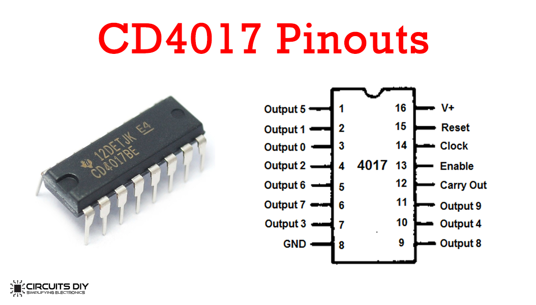
For a detailed description of pinout, dimension features, and specifications download the datasheet of CD4017
LM358 Pinout
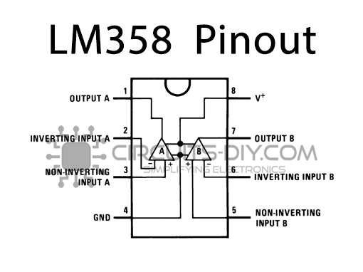
For a detailed description of pinout, dimension features, and specifications download the datasheet of LM358
RF Remote Control Circuit
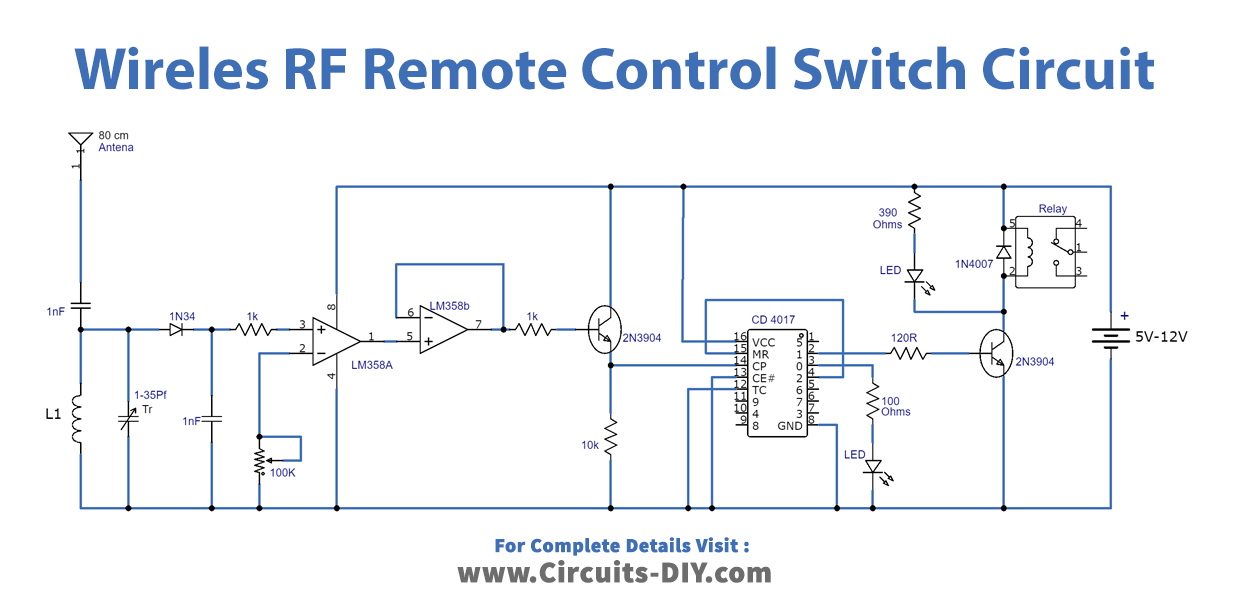
Working Explanation
The circuit that appeared here is simple to build and utilizes extremely low-cost and ordinarily accessible parts. The circuit has additionally a good range of up to 20 meters. A relay switch is utilized at the yield of the circuit, which can be associated with the appliances to perform them switch ON/OFF. The entire undertaking contains two sections, which are an FM transmitter and an RF receiver. For good outcomes utilize a good quality FM transmitter with the circuit. We have utilized our best FM transmitter circuit with a 9V battery as a transmitter with this receiver and it was working well.
The receiver circuit just detects the RF signals so there is no requirement for a microphone with the transmitter. The receiver circuit can be worked with 3V to 12V DC. The present utilization of the circuit is extremely low and in backup mode, the circuit consumes just 400µA because of which it is perfect to be worked with batteries. The Coil L1 in the receiver circuit is a hand-made air-cored coil having 6 turns of
Applications and Uses
The Wireless RF remote Control ON/OFF Switch is used as a switch for your fan, lights, or other electronic apparatuses even if you are in another room.