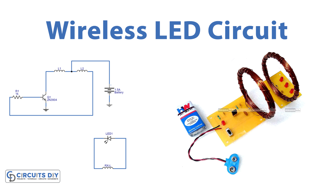
Nowadays in the field of electronics, wireless power transmission is the most wanted and demanding technology. It is a process to supply power via airgap, without any physical connection. There are two parts to it, the transmitter and the receiver. The transmitter generates a high-frequency electromagnetic field that transmits power to the receiver without any physical connection. Then the receiver extracts the magnetic field to the electrical load. Here we design a simple circuit to make glow an LED without a physical wire connection. It can provide energy to the LED with the help of Inductive coupling, here wireless transmission of electrical energy happens through magnetic flux coupled coils.
Hardware Required
| S.no | Component | Value | Qty |
|---|---|---|---|
| 1. | NPN Bi-Polar Junction Transistor | 2N3904 | 1 |
| 2. | Resistor | 1KΩ | 1 |
| 3. | Tx-Coil (30 SWG (Standard Wire Gauge) Enameled Copper Wire with 6CM dia 15 Turns + Center Tap + 15 Turns) | – | 1 |
| 4. | Rx-Coil (30 SWG (Standard Wire Gauge) Enameled Copper Wire with 6CM dia 30 Turns) | – | 1 |
| 5. | LED | – | 1 |
| 6. | Connecting Wires | – | – |
| 7. | Battery | 1.5V | 1 |
Circuit Diagram

Working Explanation
Here as we know for wireless transmission we need two main circuits, one is an energy transmitting circuit the other is a receiver circuit. For this prototype, we have used a single LED. As we can see in the circuit. Tx-Coil (Transmitter) is made of 30 SWG (Standard Wire Gauge) enameled copper wire with a 6CM diameter of 15 turns + center tap + 15 turns. The same kind of enameled copper wire with 6CM dia 30 turns is used to make the Rx-Coil (Receiver).
In the transmitter circuit, the 2N3904 NPN bi-polar junction transistor is used for low-power switching. Here the bias is applied (1.5V) to the transmitter coil center tap terminal, then the transistor Q1 makes it a high-frequency switching pulse. Because of this Tx-coil gets energized and starts making an alternating magnetic field.
Now nearby placed Rx-Coil receives magnetic flux and makes inductive coupling. Which will induce the flow of current/voltage and the LED starts glowing. As we are using a single LED at the receiver, so we don’t need to increase the transmitter circuit bias to 1.5V. This receiver circuit works around three inches only from the transmitter circuit.
Applications
Can be used in different places for decoration purposes.

