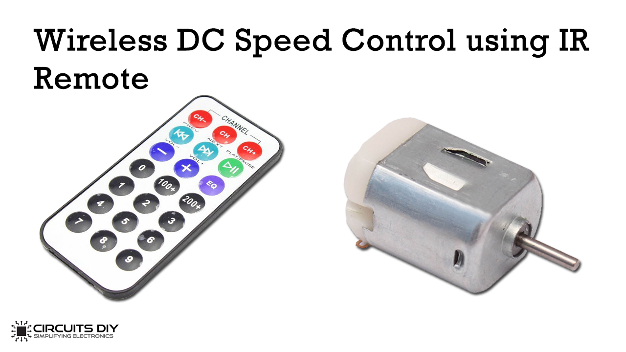
This article comprises the method of controlling the speed of a DC motor using an IR Remote OR TV Remote control without the use of any wire. The method described below does not use any sort of microcontroller. For this, you just need some basic things along with the 555 timers. By using this method, you can control DC motor speed at five different levels as well as you will be able to control anything like LED, Bulb, etc.

Hardware Components
The following components are required to make Wireless DC Motor Speed Control Circuit
| S.No | Component | Value | Qty |
|---|---|---|---|
| 1. | Breadboard | – | 1 |
| 2. | DC Supply | 12v | 1 |
| 3. | Wires | – | 1 |
| 4. | IR Sensor | TSOP1738 | 1 |
| 5. | IC | CD4017 | 1 |
| 6. | IC | NE555 Timer | 2 |
| 7. | Diode | 1N4007 | 10 |
| 8. | NPN Transistor | BC547 | 1 |
| 9. | Transformer | 12-0-12V | 1 |
| 10. | DC Motor | – | 1 |
| 11. | Electrolytic Capacitor | 1uF, 4.7uF, 470uF | 1 |
| 12. | Ceramic Capacitors | 1nF, 100nF | 1, 2 |
| 13. | Resistors | 10, 100, 220, 330, 470, 680, 1k, 4 .7k, 10k, 220k OHM | 1 |
| 14. | LED | 5mm | 2 |
555 Pinout

For a detailed description of pinout, dimension features, and specifications download the datasheet of 555 Timer
CD4017 Pinout

For a detailed description of pinout, dimension features, and specifications download the datasheet of CD4017
Circuit Diagram

Working
The motor control circuit uses TSOP1738 IR receiver U1 which works by detecting the signals given by an IR or any TV remote. First, it will receive the signals from the TV remote, then it will analyze and detect them. Then, it will activate the 555 monostable multivibrators which will produce a signal pulse when the button is pressed.
The TV remote is made in such a way that it can send 38 kHz pulses and IR radiations generate the pulses and modulate it. The pulses are detected by TSOP1738. The input is set as low which means the output will be high. It consists of 3 pins that are donated as a ground pin, VS pin, and output pin. Once the IR button is pressed, the monostable multivibrator gets activated and triggers pin2.
Different resistors are also being used that work by producing different PWMs. The DC motor used here is a 12v DC Geared motor that works with the BC547 NPN transistor.

