Introduction
For the engineers, the most difficult task is to troubleshoot the damaged devices. For the students, it’s not promising when their projects stop working. Most of the time the fault is not that big but checking that fault is difficult. Many of the times, the problem is the continuity, the wire gets a break, and the circuit gets discontinued and therefore stops working. To overcome this problem, engineers have made wire break alarms, Hence, in this tutorial, we are going to make a “Wire Break Alarm Circuit with IRFZ44N MOSFET”.
The Wire Break alarm is kind of an Emergency Alarm Circuit. It has a loop sensor in it. The loop is a simple piece of Copper Wire for shorting two terminals. In general, if we cut this wire then the circuit became open-circuited. There are many wire break alarm circuit applications.

Hardware Components
The following components are required to make a Wire Break Alarm Circuit
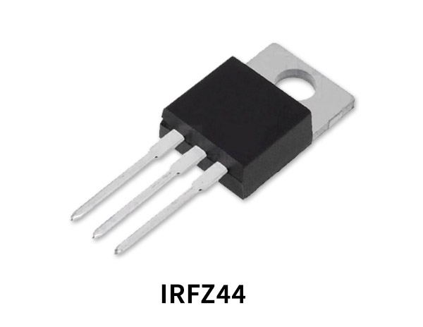
IRFZ44N Pinout

For a detailed description of pinout, dimension features, and specifications download the datasheet of IRFZ44N
Wire Break Alarm Circuit

Working Explanation
In this Wire Break Alarm Circuit, initially when the power is given, the current flows from Vcc to the ground through the loop wire. When you disconnect or cut the wire, the current starts to flow from Vcc to the gate pin of MOSFET. This triggers the MOSFET and the current starts flowing from drain to source. Hence, power up the connected load. In our alarm circuit load is LED and buzzer. So LED glows and the buzzer begins to beep. This will notify the device owner that the internal circuit has been broken.
Application and Uses
- The circuit can be designed for security purposes.
- In warning devices.
- It may be utilized in intruder alarm circuits.


