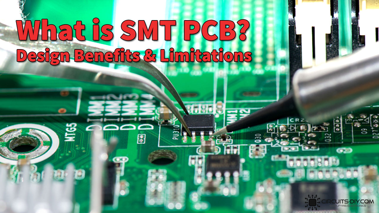
With the continuous miniaturization of consumer electronics, it has become evidently clear over the decades that a new class of components needs streamlining into the current design industry which could complement the increasing trend in technology size reduction. This need has paved the path for surface mount technology or SMT to takeover the current PCB industry. In today’s article, we will see what is SMT PCB technology & what are its design benefits & limitations.
Using PCBs dates back to as far as the late 1920s. At that time PCBs were made out of Bakelite, Masonite, or plain pieces of wood. You could drill holes in the boards and rivet them with brass wires. With the passage of time & development in PCB technology, the through-hole components gained traction. It allowed a large amount of active & passive components to be connected directly on the board without sacrificing a huge amount of workable space. Surface mount technology (SMT PCB) makes it possible to produce more reliable assemblies at a reduced weight, volume, and cost.
What is SMT PCB Technology?
Surface Mount Technology is a method for constructing electronic circuits in which SMC components mount directly onto the surface of the Printed circuit board. Electronic devices made for this purpose are called surface mount devices or SMDs.

In an SMT PCBA, the solder joint forms the physical & mechanical connections. Also, the bonding of the solder joint is to the surface of a conductive landing pattern.
Types of SMT PCBA
Incorporating with PCBs & active/passive SMCs. SMT PCBs are of 3 major types:
- Type I — Full SMT board with parts on one or both sides of the PCB board.
- Type II — Surface mount Chip components are on the secondary side of the PCB board. Active SMCs or DIPs are on the primary side of the board.
- Type III — This type of SMT PCBA uses passive chip SMCs on the secondary side of the PCB board. But the primary side of the board only uses DIP parts.

Design Benefits of Using SMT PCB Technology
1) Low Production Cost
Due to enhanced production equipment & the lower packaging material consumption. The packaging cost of most SMT components has been lower than that of THT components with the same type and function

2) Great High Frequency Effects
Since the components have no leads or short leads. The parameter distribution of the circuits is naturally lower and the RF interference is also low.
3) Less Prone To Design Errors
Another benefit of using SMT components is that they are less prone to design and assembly errors. During assembly, leads of components need not be cut short, so that the whole duration of the process is short and the production efficiency goes up while reducing errors.
4) Miniaturization of Components Saves Space
Another advantage of SMCs is that the geometric size and volume of the SMT electronic component is much smaller than that of through-hole components. THT parts can be generally reduced by 60% – 70%, and some components can even be reduced by 90% in size and volume.

5) Increases Production Yield & Efficiency
Since the standardization, serialization and consistency of welding conditions of chip components make SMT highly automatic. The component failure by welding process will be low and the reliability will improve.
Disadvantage of Using SMT PCB Technology
- High wattage parts do not pair well with SMT PCBA as it will lead to excess thermal dissipation which may damage the SMDs on the PCB board.
- Since SMT components are of extremely small size, their repair work can be a lot more complex than THT components.
- Another disadvantage of using SMT in PCBA is that the SMT PCB cards cannot be subject to roughhousing or rough handling.
- The technical complexity of SMT parts requires high training and learning costs.
- Another disadvantage of using SMT is the incompatibility between different SMT parts. There are also specific claims of some features failing to fit or be inconsistent with each other when using SMT.


