In this tutorial, we are going to make a “Hartley oscillator Circuit”.
It is difficult to provide individual power supply sources to each component in the circuit because most of the time when we are dealing with different electronic circuits and microprocessors or microcontrollers, they require a source of signal with specific frequency and amplitude, which may range from a few Hz to several GHz. Therefore, we use Oscillator circuits to provide different levels of signals to different circuit elements. An oscillator is a circuit that produces a continuous, repeated, alternating waveform without any input. Oscillators convert unidirectional current flow from a DC source into an alternating waveform that is of the desired frequency, as decided by its circuit components.
Here simple Hartley Oscillator circuit is designed to provide a wide range of sinusoidal output. A Hartley Oscillator is a type of harmonic oscillator. The oscillation frequency for a Hartley Oscillator is determined by an LC oscillator. Every sinusoidal Oscillator circuit will have a Tank circuit, Amplifier circuit, and feedback path, here the feedback should be positive and the oscillator circuit must obtain the undamped output. Hartley oscillators are typically tuned to produce waves in the radiofrequency band. The distinguishing feature of a Hartley oscillator is that the tuning circuit consists of a single capacitor in parallel with two inductors in series (or a single tapped inductor), and the feedback signal needed for oscillation is taken from the center connection of the two inductors. This circuit is capable to produce a sinewave signal frequency range from 20KHz to 90KHz.
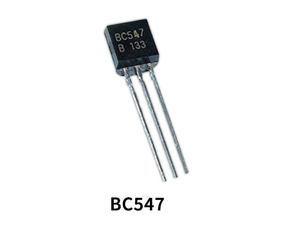
Hardware Component
The following components are required to make Hartley Oscillator Circuit
| S.no | Component | Value | Qty |
|---|---|---|---|
| 1. | Transistor | BC547 | 1 |
| 2. | Inductor | 10mH, 20mH | 1, 1 |
| 3. | Ceramic Capacitor | 10pF, 100nF, 100pF | 1, 1, 2 |
| 4. | Resistor | 100KΩ, 5KΩ, 1KΩ, 10KΩ | 1, 1, 1, 1 |
| 5. | Connecting Wires | – | – |
| 6. | Battery | 9V | 1 |
BC547 Pinout
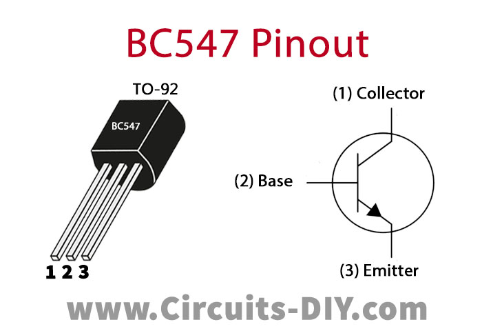
For a detailed description of pinout, dimension features, and specifications download the datasheet of BC547
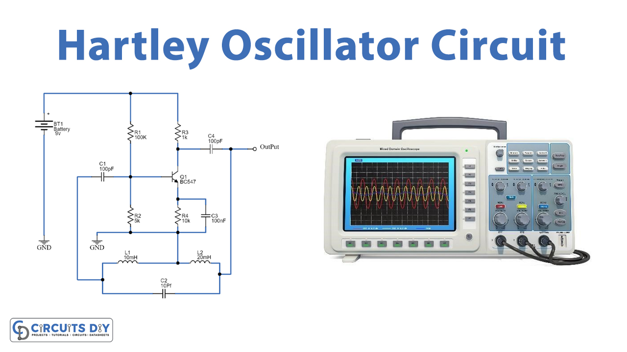
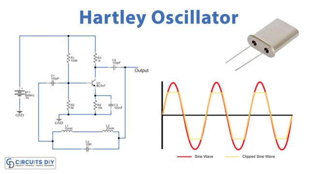
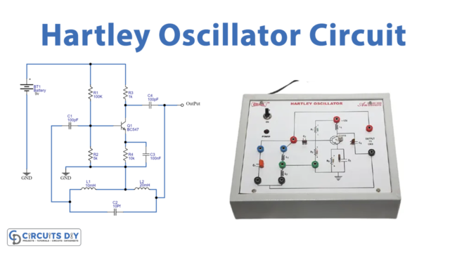
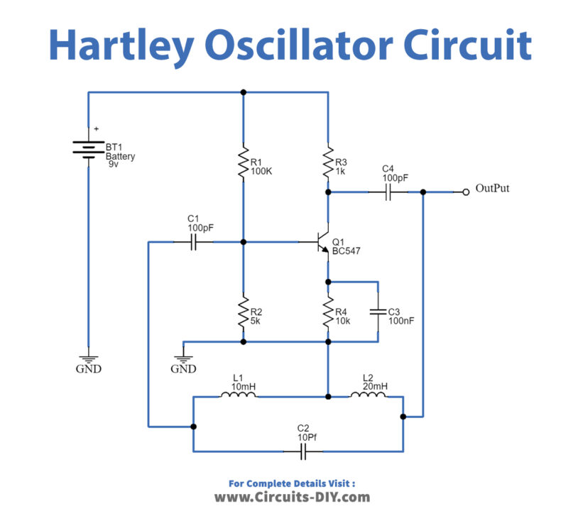
Hartley Oscillator Circuit
Working Explanation
Hartley Oscillator circuit has a tank circuit with two Inductors and one Capacitor. The R3 is the collector resistor while the emitter resistor R4 forms the stabilizing network. Further, the resistors R1 and R2 form the voltage divider bias network for the BC547 transistor and act as a single transistor amplifier in the common-emitter CE configuration. Output is taken from the Collector terminal of the BC547 transistor through output coupling capacitor C4. The feedback path is connected between collector and base through a tank circuit. L1 and L2, and the capacitor C2 which forms the tank circuit. The capacitors C1 and C4 are the input and output decoupling capacitors while the emitter capacitor C3 is the bypass capacitor used to bypass the amplified AC signals.
When we apply a power supply to this circuit, the transistor starts to conduct, which charges the capacitor C2. As collector current starts rising and charges the capacitor C in the tank circuit. On acquiring the maximum charge feasible the Capacitor gets full charge, and C starts to discharge via the inductors L1 and L2. These charging and discharging cycles result in the damped oscillations in the tank circuit.
The oscillation current in the tank circuit produces an AC voltage across the inductors L1 and L2 which are out of phase by 180o as their point of contact is grounded. The output of the amplifier is applied across the inductor L1 while the feedback voltage drawn across L2 is applied to the base of the transistor. Thus, the amplifier’s output is in-phase with the tank circuit’s voltage and supplies back the energy lost by it while the energy fed back to the amplifier circuit will be out-of-phase by 180o. The feedback voltage which is already 180o out-of-phase with the transistor is provided by an additional 180o phase shift due to the transistor action. Hence total 360º phase shift is produced between the input and output signal of the tank circuit.
Hartley Oscillator Circuit Formula
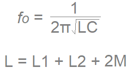
C = Capacitor in tank circuit (C2)
L = Total value of Inductor L1 and L2 in tank circuit and 2M is mutual inductance (only use 2M if two coils L1, L2 are wound on the same core).
Applications
This Hartley oscillator circuit is widely used in radio communication and audio system.


