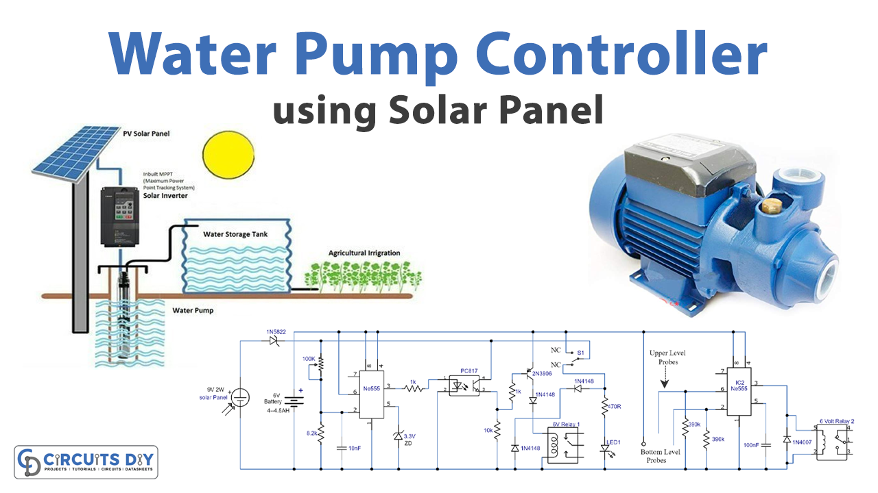
This is a water pump controller circuit powered by a solar panel. Also, there is a battery charge and discharge operation for the night. For this case, the circuit uses two NE555 timer ICs.
Hardware Required
| S.no | Component | Value | Qty |
|---|---|---|---|
| 1. | Solar panel | 9V/2W | 1 |
| 2. | Battery | 6V – 4.5AH | 1 |
| 3. | Optocoupler | PC817 | 1 |
| 4. | IC | NE555 Timer | 2 |
| 5. | PNP Transistor | 2N3906 | 1 |
| 6. | Diode | 1N4148, 1N4007, 1N5822 | 3, 1, 1 |
| 7. | Zener Diode | 3.3V | 1 |
| 8. | Variable Resistor | 100KΩ | 1 |
| 9. | Resistor | 470Ω,1KΩ,10KΩ,8.2KΩ,390KΩ | 1,2,1,1,2 |
| 10. | Probes | – | 2 |
| 11. | Ceramic Capacitor | 10nF, 100nF | 1, 1 |
| 12. | Switch | – | 1 |
| 13. | Relay | 6V | 2 |
| 14. | LED | – | 1 |
Circuit Diagram

Circuit Explanation
Firstly, the circuit is divided into two parts. At first, charging the battery from the solar panel takes place. Whereas, the other half of the circuit is the detection of water level and turning the motor ON/OFF, accordingly. In the beginning, the circuit is operated through a separate power supply of 7.5V. After that, set 100KΩ variable resistor such that the LED lights up. Then, remove the battery supply and connect the 4AH or 4.5AH sealed lead acid battery to the circuit.
Secondly, for the other part of the circuit, connect probes to the ICs and water tank. For this purpose, attach the two probes at the highest and the lowest level of the tank, respectively. After that, the circuit operation starts. During the daytime, the solar panel directly powers the circuit. In the meanwhile, IC1 charges the battery through the solar panels attached. Subsequently, the IC2 checks the water level in the tank. If the tank is full, IC2 turns OFF the relay switch, hence, turning the motor OFF. Whereas with the tank being empty, the relay is turned ON, thus, the motor starts working.
Furthermore, for the nighttime, the battery is already charged to power up the circuit.
Application
- Automated water pump
- Solar panel home automation