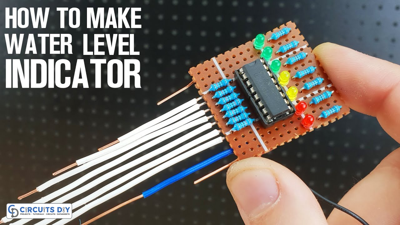
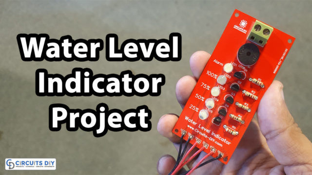
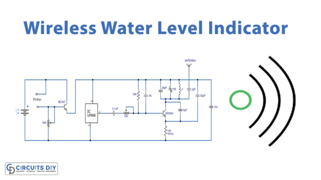
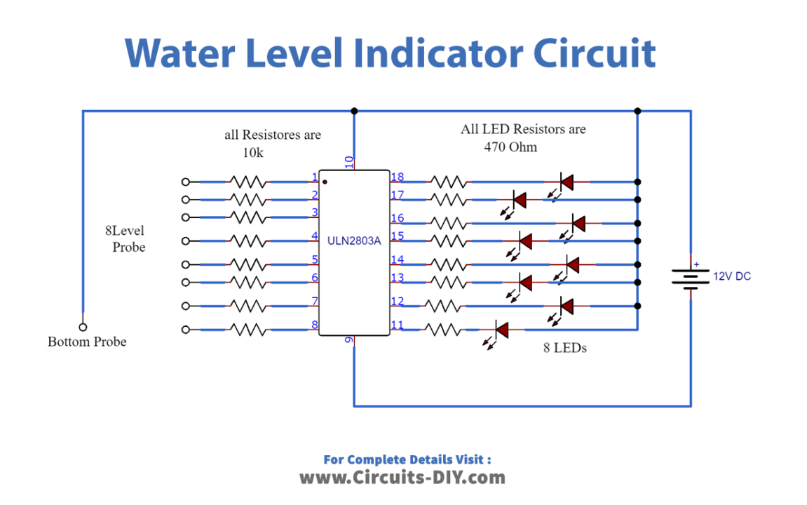
This project of water level indicator detects and indicates 8 different levels of water in a container. For this case, the circuit uses IC ULN2803 and 8 LEDs to represent each level.
Hardware Required
Circuit Diagram
Circuit Explanation
Since, the circuit involves only one IC, few LEDs, and just resistors, hence, the working of the circuit is very simple. The IC ULN2803 is an array IC containing eight Darlington pair transistors. Furthermore, a positive rail is attached at the bottom of the container as the bottom probe. Whereas, the 8-level probes are such connected that each probe links the base of transistors in the IC from PIN01 to PIN08. Also, these probes are attached at different levels/heights of the container to be measured. After that, the LEDs are attached to IC PIN 11 to PIN 18 along with its current limiting resistors of 470Ω.
The working is such that the electrical connection is set up between the bottom probe and one of the 8-level probes. The water level reaches a certain level of the probe; hence, the corresponding probe connects with the bottom probe. Therefore, the LED, associated with the probe and transistor, lights up.
Application
- Small electronic projects water level detection


