Overview
God has bestowed onto humanity the greatest of all gifts: water. Even still, sometimes it takes human creativity to make the most of God’s benefits. As an example, water is used in both commercial and industrial settings. Therefore, keeping an eye on the massive water supply is important. And now we have the flow sensor. In order to keep track of how much water is supplied and used, the flow rate must be measured. Flow sensors are put in the water supply or pipes to measure how much and how fast the water moves through them.
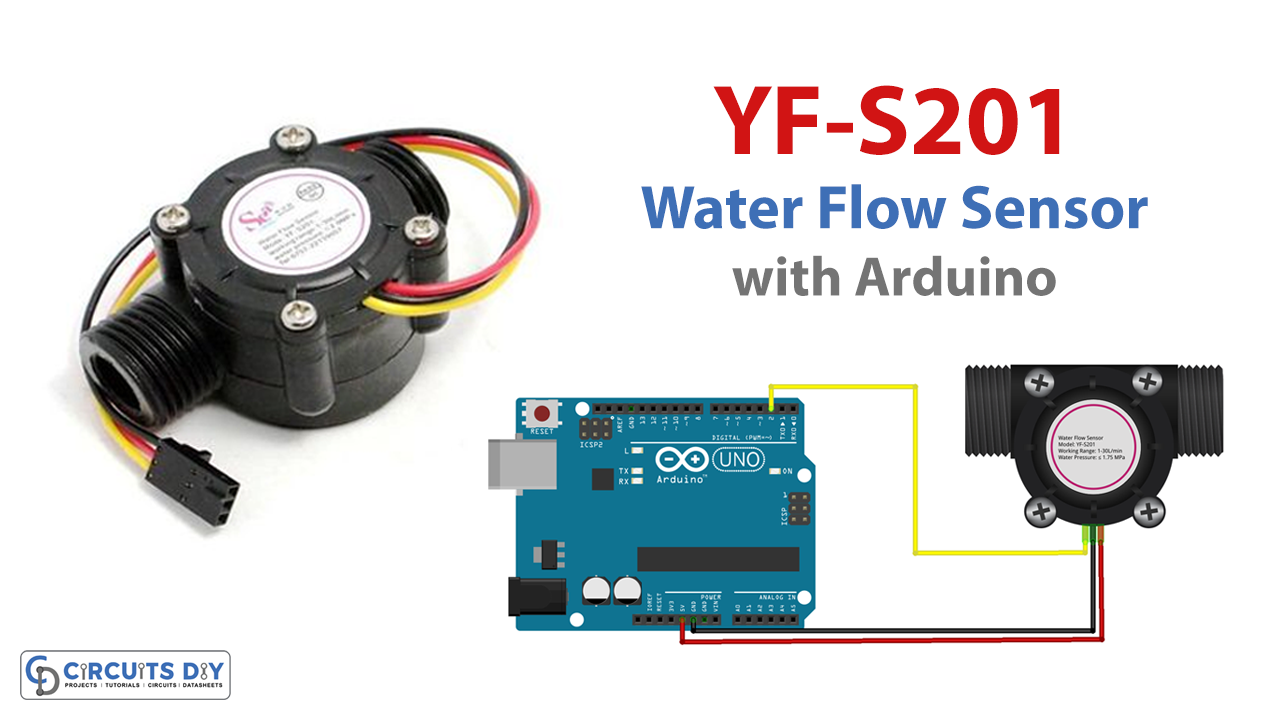
In this tutorial, we will interface “Water Flow Sensor YF-S201 with Arduino” to measure its flow rate. So let’s get started!
Hardware Required
| S.no | Components | Value | Qty |
|---|---|---|---|
| 1 | Arduino | UNO | 1 |
| 2 | USB Cable | Type A to B | 1 |
| 3 | Water Flow Sensor | YF-S201 | 1 |
| 4 | Jumper Wires | – | – |
Circuit Diagram

Connection Table
| Arduino | Water Flow Sensor YF-S201 |
|---|---|
| GND | GND |
| 5V | Vcc |
| A2 | SIG |
| D2 | CLK |
Arduino Code
/*
Arduino Water flow meter
YF- S201 Hall Effect Water Flow Sensor
Water Flow Sensor output processed to read in litres/hour
*/
volatile int flow_frequency; // Measures flow sensor pulses
unsigned int l_hour; // Calculated litres/hour
unsigned char flowsensor = 2; // Sensor Input
unsigned long currentTime;
unsigned long cloopTime;
void flow () // Interrupt function
{
   flow_frequency++;
}
void setup()
{
   pinMode(flowsensor, INPUT);
   digitalWrite(flowsensor, HIGH); // Optional Internal Pull-Up
   Serial.begin(9600);
   attachInterrupt(0, flow, RISING); // Setup Interrupt
   sei(); // Enable interrupts
   currentTime = millis();
   cloopTime = currentTime;
}
void loop ()
{
   currentTime = millis();
   // Every second, calculate and print litres/hour
   if(currentTime >= (cloopTime + 1000))
   {
      cloopTime = currentTime; // Updates cloopTime
      // Pulse frequency (Hz) = 7.5Q, Q is flow rate in L/min.
      l_hour = (flow_frequency * 60 / 7.5); // (Pulse frequency x 60 min) / 7.5Q = flowrate in L/hour
      flow_frequency = 0; // Reset Counter
      Serial.print(l_hour, DEC); // Print litres/hour
      Serial.println(" L/hour");
   }
}
Working Explanation
This sensor consists of a Hall effect sensor and a plastic encasement, onto which is embedded a magnetized turbine wheel. The magnet flux causes interference with the hall sensor as the turbine wheel rotates while water runs through the pipeline. Hall effect sensors generate a pulse signal due to the interference they experience; this signal may then be used to determine the amount of water flowing through the sensor.
The serial monitor in the Arduino software displays the measured water flow rate in liters per hour as a result of running the above code for the water flow sensor.
Code Explanation
- We start the sketch by defining some variables which would be utilized in the sketch later.
- We declare the sensor pin as the input in the void setup. After that, we execute the attachInterrupt() instruction. An interrupt number is sent as the first parameter to attachInterrupt() to translate the real digital pin to the appropriate interrupt number. sei() is used to enable interrupt. Following that, we measure the current time using millis() function. Then we store that current time in the variable named cloopTime.
- The output pulse frequency of the YF-S201 Water Flow Sensor can be determined using the calculation in the void loop, according to the formula: Pulse frequency = 7.5 x Q (flow rate in L/m). Then, using another formula, we measure the flow rate in L/hr and print that on the serial monitor using the Serial.print function.
Application and Uses
- Production plants.
- Commercial and public water supply systems.