Introduction
Water is indeed the greatest blessing for human beings from our lord. However, sometimes humans need to use their brains to use the gifts properly. For example, water use is everywhere, from commercial buildings to industries. Thus, the large amount of water supply needs monitoring. And, here comes the flow sensor. It is necessary to measure the rate of flow of water to keep track of how much is provided and utilized. Water flow sensors are put at the water source or pipelines to monitor the flow of water and determine how much water goes through the pipe. Hence, this tutorial is about “Water Flow Sensor Interfacing with Arduino – Measure Flow Rate.”
Brief Overview
Hardware Overview
The sensor consists of a plastic valve that allows water to pass and serves as the water flow sensor. A water rotor and a hall effect sensor allow for the detection and measurement of water flow.
Working Principle
The Hall effect is the primary operating mechanism of this sensor. The movement of the rotor induces a voltage differential in the conductor in this sensor, according to this principle. This generated voltage difference occurs in the opposite direction of the electric stream.
When the moving fan rotates owing to the flow of water, the rotor turns, inducing electricity. The hall effect sensor measures this generated voltage and shows it on display.
YF-S201 Water Sensor
The YF-S201 is a water sensor that is technically intended to monitor the flow rate and volume of the required water through pipes. It is a low-cost water flow sensor made from a copper body and a water rotor. The sensor also has an internal circuit of the Hall effect sensor, which operates based on electromagnetism and delivers pulses at the output pin. It is a low-power and MCU-compatible device with a maximum flow rate of 30 liters per minute. A compact, high-accuracy sensor is used for flow monitoring in anything from commercial to industrial level.
Hardware Required
| S.no | Components | Value | Qty |
|---|---|---|---|
| 1 | Arduino UNO | – | 1 |
| 2 | USB Cable Type A to B | – | 1 |
| 3 | Water Flow Sensor | YF-S201 | 1 |
| 4 | Jumper Wires | – | – |
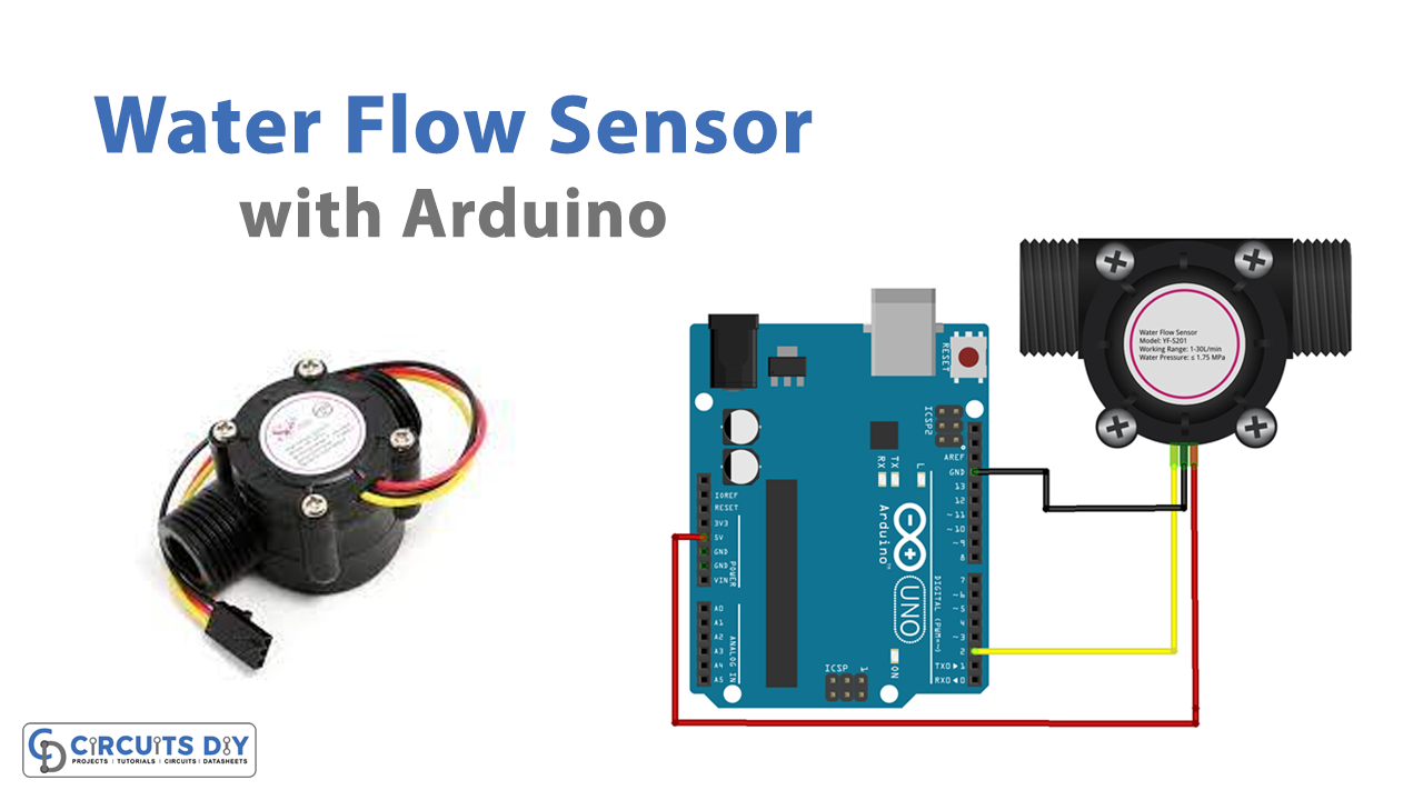
Circuit Diagram

Connection Table
| Arduino UNO | Water Flow Sensor |
|---|---|
| GND | GND |
| 5v | Vcc |
| D2 | SIG |
Arduino Code
/*YF- S201 water Flow sensor code for Arduino */
const int Output_Pin = 2;

volatile int  Pulse_Count;
unsigned int  Liter_per_hour;
unsigned long Current_Time, Loop_Time;

void setup()
{
   pinMode(Output_Pin, INPUT);
   Serial.begin(9600);
   attachInterrupt(0, Detect_Rising_Edge, RISING);

   Current_Time = millis();
   Loop_Time = Current_Time;
}

void loop ()
{
   Current_Time = millis();
   if(Current_Time >= (Loop_Time + 1000))
   {
      Loop_Time = Current_Time;
      Liter_per_hour = (Pulse_Count * 60 / 7.5);
      Pulse_Count = 0;
      Serial.print(Liter_per_hour, DEC);
      Serial.println(" Liter/hour");
   }
}
void Detect_Rising_Edge ()
{
   Pulse_Count++;
}
Working Explanation
This Arduino code for the water flow sensor detects the water flow rate in liters per hour and shows the observed value on the Arduino IDE’s serial monitor. When water goes through the valve, it starts to rotate the rotor. By doing this, the change in the motor’s speed can be seen. The hall effect sensor calculates this change and outputs it as a pulse signal. Thus, it is possible to gauge the water’s flow rate.
Code Explanation
- Start the sketch by defining some variables which would be utilized in the sketch later.
- In the void setup, declare the input pin. Execute the attachInterrupt() instruction. An interrupt number is sent as the first parameter to attachInterrupt(). To translate the real digital pin to the appropriate interrupt number.
- The output pulse frequency of the YF-S201 Water Flow Sensor may be determined using the following calculation in the void loop, according to the datasheet: Pulse frequency = 7.5 x flow rate
Application and Uses
- Industrial plants.
- Commercial and public water supply systems.