Introduction
This article is about the voltage follower circuit. A voltage follower is a circuit that provides the voltage gain of unity. In other words, you can say, its output voltage is the same as the input voltage but with a higher current. This means these circuits generate no voltage gain but a current gain. If you have a great interest in electronics and its engineering, you might have heard the term buffer. A buffer is basically the circuit that draws a little current because of high impedance, and therefore, a voltage follower circuit can also act as the buffer. Now, in this tutorial, we are going to “Voltage Follower Circuit Using op-amp 741”
Specifications of 741 opamp IC
- Power Supply: Requires a Minimum voltage of 5V and can withstand up to 18V
- Input Impedance: About 2 MΩ
- Output impedance: About 75 Ω
- Voltage Gain: 200,000 for low frequencies (200 V / mV)
- Maximum Output Current: 20 mA
- Recommended Output Load: Greater than 2 KΩ
- Input Offset: Ranges between 2 mV and 6 mV
- Slew Rate: 0.5V/µS (It is the rate at which an Op-Amp can detect voltage changes)
Pinouts of 741 IC
| PINS | Details |
|---|---|
| 1 ( Offset N1) | Offset pin 1 is for external input offset voltage change |
| 2 ( Inverting Input) | Inverting input for applying the inverting input voltage |
| 3 (Non-Inverting Input) | Non-inverting input pin for applying a non-inverting input voltage |
| 4 (-Vcc) | Vcc- is for applying negative DC supply |
| 5 (Offset N2) | Offset Null 2 is for external input offset voltage adjustment |
| 6 (Output) | Output pi is for obtaining output voltage |
| 7 (+Vcc) | Vcc+ is for applying a positive DC supply |
| 8 (NC) | This pin is for no connection i.e. it is to be kept open |
Hardware Required
| S.no | Component | Value | Qty |
|---|---|---|---|
| 1. | Operational Amplifier IC | LM741 | 1 |
| 2. | Variable Resistor | 10KΩ | 1 |
| 3. | Resistor | 1K | 1 |
| 4. | Battery | 9V | 1 |
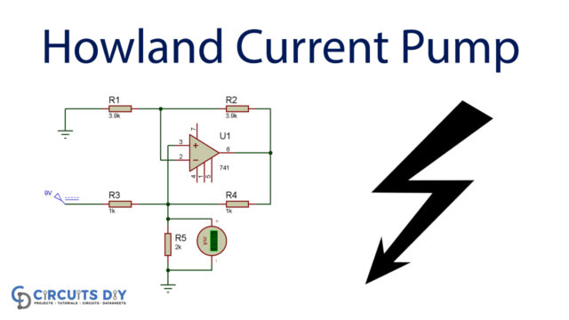
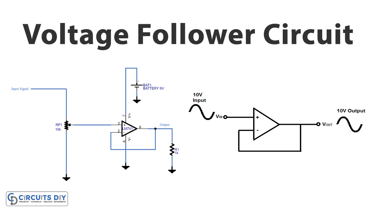
Circuit Diagram
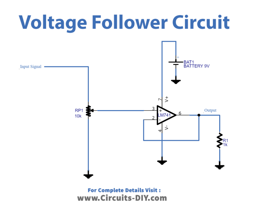
Working Explanation
In this Voltage Follower Circuit Using op-amp 741, we first apply the input signal to the Non-inverting pin of an IC while the Inverting pin 2 is connected as the negative feedback with output pin 6. Bias pins, pins 7 and 4 are wired with battery, and output is hooked up to the load resistor. The input impedance of operational amplifier IC 741 will be high and because of the high input impedance, it will draw very low current from the input source and hence provides high current output to the load.
Application and Uses
- The voltage follower can work as the buffer circuit.
- We can use it in active filters.
- Also, can be employed in bridge circuits, etc.