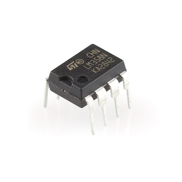
Reverse parking can get a little tricky or difficult and there are more risks of bumping the car into something which can cause damage so to solve this problem we have come up with this tutorial. In this tutorial, we are making a Vehicle Reverse Parking Helper project. This circuit is built around an LM358 IC, it consists of two operational amplifiers but we are only using one here. The purpose of this circuit is to help you in reverse parking of any vehicle by providing a visual indication by lighting up an LED when the vehicle is close to any obstacle in a reverse way. You can also get a sound indication by adding any buzzer like a piezo buzzer between the ground and pin 1 of the IC.
Components description and Placement:
Apart from this IC, there are some other components used in this circuit. A 20K variable resistor is used to adjust the sensitivity of the circuit. Two pairs of IR LEDs are used to detect the obstacles; each pair is placed at the lower backside of the vehicle. Each pair consists of two IR LEDs of which is a transmitter and the other is the receiver. Both the LEDs on a pair are supposed to be placed side by side to detect any obstacle in their way. The IR rays generated from these IR LEDs are received by Photodiodes.

Hardware Components
The following components are required to make Vehicle Reverse Parking Circuit
| S.no | Component | Value | Qty |
|---|---|---|---|
| 1. | Input Supply DC | 5-12V | 1 |
| 2. | IR LED | – | 2 |
| 3. | Photodiode | – | 2 |
| 4. | IC | LM358 | 1 |
| 5. | Resistor | 220RΩ, 10KΩ, 470RΩ | 2, 2, 1 |
| 6. | LED | – | 1 |
| 7. | Variable Resistor | 20KΩ | 1 |
LM358 Pinout

For a detailed description of pinout, dimension features, and specifications download the datasheet of LM358
Vehicle Reverse Parking Circuit

Working Explanation
The IC LM358 is working in comparator mode here. IR transmitter LED generated IR rays continuously and when any obstacle crosses it breaks the contact of IR LED and the photodiode. Now the rays bounce back and are received by the receiver IR LED. When the signal is received by the IR receiver LED, the LM358 IC starts working, and pin 1 goes high which activates the LED connected at this pin. This circuit can be operated at DC voltages ranging from 5 to 12 volts.


