Introduction
We are all aware of USBs. You might have used it or maybe still use it to store data. Our article today is about that. In this tutorial, we are going to make a “USB to UART circuit”. In order to transfer or receive serial data from a USB port into serial data that may be received or sent by a UART interface, there is an integrated circuit known as a USB to UART converter. There are at least ground, Rx, and Tx outputs on this little device, which connects to your USB port.
This circuit makes use of the FT232R. The FT232R IC is a USB-to-serial UART converter with a new security dongle function and an optional clock generator output. Other interface options include synchronous and asynchronous bit bang. The external EEPROM, clock circuit, and USB resistors have been completely integrated into the FT232R, simplifying USB to serial designs even more.
Hardware Required
| S.no | Component | Value | Qty |
|---|---|---|---|
| 1. | IC | FT232RL | 1 |
| 2. | Microcontrollers | TxD, RxD | 1 |
| 3. | USB | – | 1 |
| 4. | Electrolytic Capacitor | 10uF | 1 |
| 5. | Capacitor | 0.1uF | 2 |
| 6. | Resistor | 1KΩ, 10Ω, 560Ω | 1 |
| 7. | 2-Pin Connector | – | 1 |
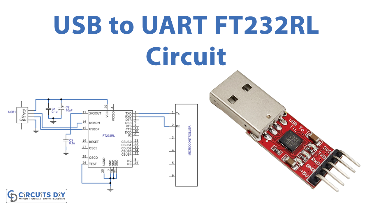
Circuit Diagram

Working Explanation
This USB to UART Circuit, which uses an FT232RL IC, has only four pins: +5V, D-, D+, and GND. The FT232 ICs’ pins 1, usbDM) and 15, usbDP are connected to the USB ports D- and D+, respectively. Pin5 of the FT232 must be connected to the microphone, and pin1 of the FT232 must be connected to the RxD pin of the microcontroller.
Application and Uses
- Embedded devices
- To interact with a development board


