Introduction
The Two-Tone Alarm Circuit is a new and unique way to get a reliable alarm system that can be set up the way you want. With its dual-tone functionality, this circuit allows users to choose between two distinct alarm sounds, providing a personalized experience and making it easier to distinguish between different types of alarms. Whether you’re looking to use it as a security alarm, a reminder alarm, or even a doorbell, the Two Tone Alarm Circuit is a versatile and practical option.
The circuit is simple to build and easy to use, making it a great choice for both beginners and experienced hobbyists. So if you’re looking for a reliable, customizable, and easy-to-use alarm system, let’s try to make one with us!
Hardware Required
You will require the following hardware for Two Tone Alarm circuits.
| S.no | Component | Value | Qty |
|---|---|---|---|
| 1. | IC | LM3900N | 2 |
| 2. | Capacitor | 1uF, 47nF | 1, 1 |
| 3. | Polar Capacitor | 220uF | 1 |
| 4. | Resistor | 2M2, 3M9, 1M0, 10K, 39K, 390K | 2, 2, 2, 1, 1, 1 |
| 5. | MOSFET | VN66AF | 1 |
| 6. | Diode | 1N4148 | 1 |
| 7. | Speaker | LS 8.8R | 1 |
Steps to make Two Tone Alarm Circuit
Follow the given circuit diagram and connections to build the circuit.
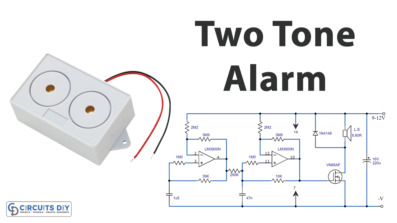
Circuit Diagram

Connections
- LM3900N IC is the main component of the circuit.
- IC1b and IC1a are Norton amplifiers.
- Capacitor C2 is connected to IC1b through resistor R9.
- Resistor R6 is connected to the inverting input of IC1b.
- Resistor R8 is connected to the non-inverting input of IC1b.
- Resistor R5 is connected between IC1a and C2, which mixes the output of IC1a with C2.
- The output of IC1b is connected to a loudspeaker through a common source amplifier using a VMOS transistor Q1.
- A 9V supply and a speaker impedance of 64-80 ohms can be connected for low-power applications.
- A 12V supply and 8-ohm speaker can be connected for high-volume applications.
Working Explanation
The circuit uses two Norton amplifiers, similar to standard operational amplifiers but relies on the relative input currents rather than input voltages to determine the output voltage.
The circuit uses an LM3900N IC, which contains four Norton amplifiers. The first amplifier, IC1b, is used in a relaxation oscillator circuit that produces the primary sound tone. This circuit works by charging capacitor C2 through resistor R9, which increases the current flowing into the inverting input of the amplifier through resistor R6.
When this current exceeds the non-inverting input bias current, the output of the amplifier switches from high to low, which causes C2 to discharge through R9. This cycle repeats, resulting in a constant oscillation.
The second amplifier, IC1a, is used in a second oscillator circuit with component values that provide oscillation at a frequency of just a few Hertz. This circuit frequency modulates the tone generator to produce a warbling effect, which makes the alarm signal more recognizable and less easily masked. The output of IC1a is mixed with C2 through R5.
The high impedance squarewave output of IC1b is connected to a loudspeaker via a common source amplifier using a VMOS transistor Q1.
The circuit can be powered by a 9V supply and a speaker impedance of 64-80 ohms for low-power applications, providing a nominal output power of 250-300 mW with current usage of 55-70 mA. A 12V supply and 8-ohm speaker can be used for high-volume applications, providing an output power of around 4 W RMS at a mean current usage of approximately 700 mA.
Final Words
A Two-Tone Alarm Circuit is explored in this article. The circuit is simple and employs low-priced components. We hope you learned something new about this circuit from this post and found it helpful. Please don’t hesitate to contact us if you have any queries or feedback.