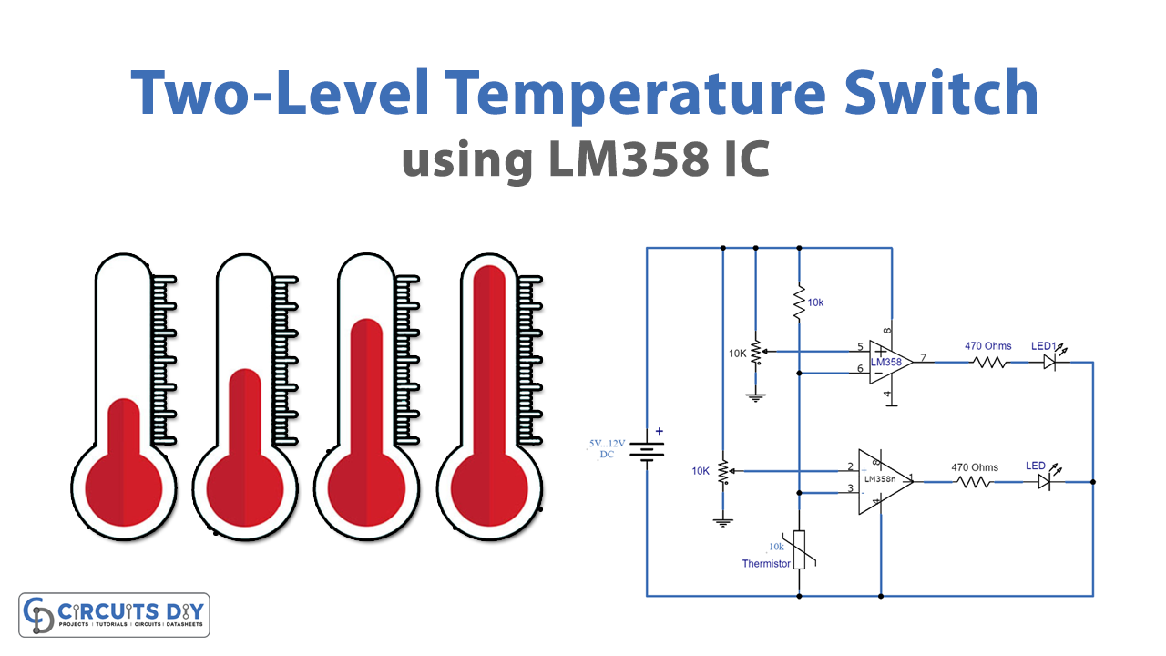
The two-level temperature switch measures two different temperature ranges. After that, the relay turns ON/OFF corresponding to the temperature level. Furthermore, the circuit includes IC LM358, transistors, diodes, and relays.

Hardware Components
The following components are required to make Temperature Switch Circuit
| S.no | Components | Value | Qty |
|---|---|---|---|
| 1. | DC Battery | 5V-12V | 1 |
| 2. | Thermistor | 10K | 1 |
| 3. | Op-amp IC | LM358 | 2 |
| 4. | Variable Resistor | 10K | 2 |
| 5. | Resistors | 10K, 470 ohms | 1, 2 |
| 6. | LED | – | 2 |
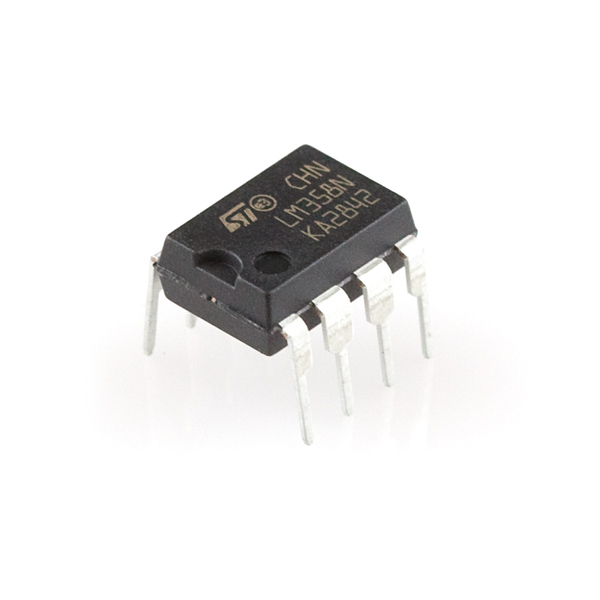
LM358 Pinout

For a detailed description of pinout, dimension features, and specifications download the datasheet of LM358
Temperature Switch Circuit

Working Explanation
The thermistor in the circuit detects the temperature and sends signals as INPUT to the two ICs. LM358 is a dual operational amplifier IC. Moreover, both ICs are working in their comparator mode. Additionally, both the op-amps are working in the circuit but with separate ICs. Also, attached to the IC is a 10KΩ variable resistor which is set to get the desired level of temperature.
Both ICs receive the same signal from the thermistor, then, IC compares the input signal with the pre-set value using a potentiometer. The IC whose comparator results in zero or less than the other outputs a HIGH signal. Subsequently, the transistor, attached to the latter IC, receives the weak signal and amplifies it. At last, the amplified signal activates the corresponding relay. Meanwhile, the diode keeps a check for polarity changes in the circuit.
Also, a relay has to be of the same voltage rating as that of the battery.
Application
Any electronic circuit that is to be operated at a certain temperature is attached to this switch circuit. Additionally, the circuit prevents from burning of the electronic circuits attached to it. It is because the circuit switches to the other relay immediately with the rise in temperature.


