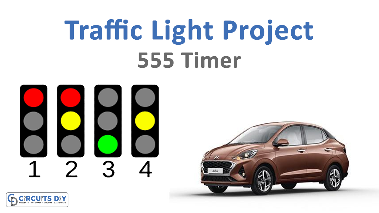
Traffic lights are utilized to control the on-street vehicular traffic. What’s more, helps to maintain a strategic distance in congested driving conditions and avoid mishaps. There are three lights on the traffic signal pole, having a diverse message for drivers. The traffic light has ended up being a stunning method to diminish the number of vehicle accidents and it adequately and intelligently controls the traffic jams in the modern era.
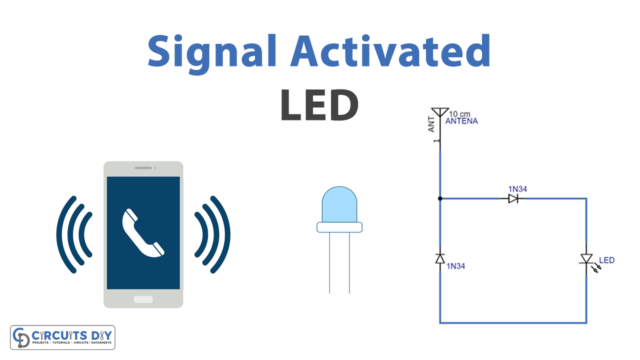
This article depicts a project of a traffic light utilizing three 555 clock timer ICs. The circuit is utilizing three shading LEDs which are red, yellow, and green same hues as you have found in the street signal traffic lights. The lighting example of the circuit is additionally the same as the traffic signal lights. The RED light requests the driver to yield at the intersection, the GREEN light gives the driver a free permit to pass through the crossing point while the YELLOW light alarms the driver to pause.

Hardware Components
The following components are required to make Traffic Light Circuit
| S.no | Components | Value | Qty |
|---|---|---|---|
| 1. | IC | NE555 Timer | 1 |
| 2. | LEDs | – | 3 |
| 3. | Switch | – | 1 |
| 4. | Resistor | 10k, 100k, 470Ω, 390Ω | 4, 4, 2, 1 |
| 5. | Power diodes | 1N4148 | 2 |
| 6. | Electrolytic capacitors | 0.1µF, 47µF, 10µF, 1000pF | 3, 2, 2, 4 |
| 7. | DC supply or Battery | 5V – 12V | 1 |
NE555 IC Pinout

For a detailed description of pinout, dimension features, and specifications download the datasheet of NE555
Traffic Light Circuit
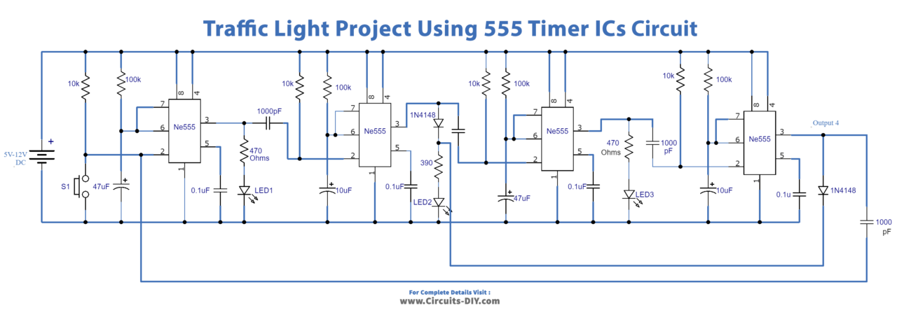
Working Explanation
The circuit is utilizing four 555 clock timer ICs, every IC is attempting to give a specific time delay. Also, the time postponement of all ICs relies upon their 100K resistors and the capacitor Cx, this implies expanding or diminishing the ON time of the LEDs. This can be balanced with the 100K resistor and capacitor Cx (47µF and 10µF). They can work with 5V to 12V DC. At the moment when you are working on the circuit with lower voltages for instance 5V or 6V and the LEDs are not getting brighter on these voltages, at that point change the estimation of all the 470 ohms resistors and 390 ohms resistor to 240 ohms.
At the point when the switch S1 squeezes, the red LED gets actuated for a few moments, after a couple of moments the red LED will become deactivated and the yellow LED will get enacted for a less timespan as contrast with the red LED. When the yellow LED turns off the green LED will get enacted. And when the green LED turns OFF on the other hand the yellow LED will actuate and afterward the red LED activates, and this procedure will ceaselessly rehash until the power source is separated.
Applications and Uses
- Optimum control of fluctuating traffic volumes, for example, over soaked or bizarre burden conditions.
- Improve the vehicular throughput
- Maximizes the traffic stream
- Typical applications for these signs are slant crossing points, explicit multi-path control, left-turn pocket signals, or different areas where traffic monitoring is obligatory.