Traffic lights are also named stoplights, road traffic lamps, traffic signals, and stop-and-go lights. Which are signaling devices placed at road crossings, everyday pedestrian crossings, and other locations to control competing flows of traffic. Traffic lights have been fixed all over the world in many cities. Traffic light control assigns the right way to the road users by using lights in normal colors (red–amber/yellow-green). The traffic light control system uses a worldwide color code (a specific color order to enable color recognition for those who are color blind). Here we design a traffic light circuit timer ICs 555 and three LED indicators. This circuit drives three LEDs with a different time delays to provide stop, wait, and go signals on road.
Hardware Required
| S.no | Component | Value | Qty |
|---|---|---|---|
| 1. | IC | NE555 Timer | 2 |
| 2. | Resistor | 470Ω,220Ω | 2 |
| 3. | Variable Resistor | 100KΩ | 1,2 |
| 4. | Capacitor | 100uF | 2 |
| 5. | Red LED | – | 1 |
| 6. | Yellow LED | – | 1 |
| 7. | Green LED | – | 1 |
| 8. | Connecting Wires | – | – |
| 9. | Battery | 12V | 1 |
Circuit Diagram
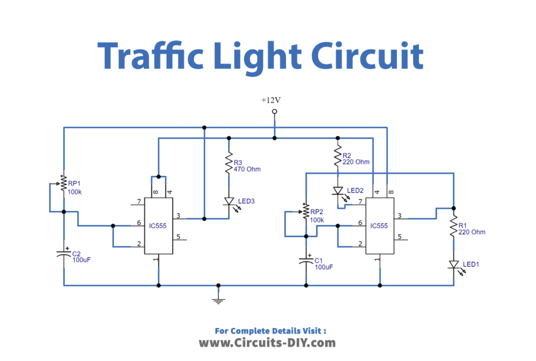
Working Explanation
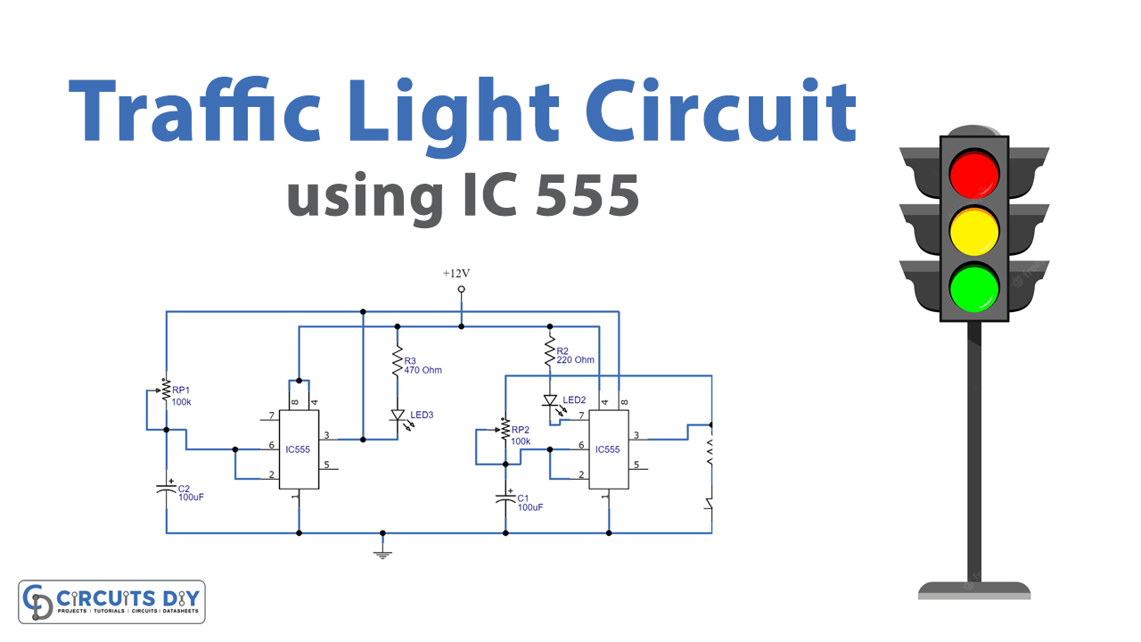
As we can see in the circuit, the timer IC is a main part of the circuit. Here two timer ICs are placed and biased with a 12-volt power supply. The left side timer provides output through Red LED, and the right side timer LED provides output through the yellow LED and Green LED. Here the yellow LED output is controlled by a discharge pin, Vcc supply for this IC provides through output and timer elements of the left side timer IC 555. We can vary the time delay between LEDs by varying VR1 and VR2 variable resistors. In this circuit, two timer ICs control voltage pin 5 left as no connection.
Now the red LED has an equal on-off period and when it is off, the first 555 delivers power to the second 555. This illuminates the Green LED and then the second 555 changes state to turn off the Green LED and turn on the yellow LED for a short period of time. Here before the first 555 changes state to turn off the second 555 and turn on the red LED. This circuit also shows how to connect LEDs high and low to a 555 and also turn off the 555 by controlling the supply to pin 8. Connecting the LEDs high and low to pin 3 will not work and since pin 7 is in phase with pin 3, it can be used as an advantage in this design.
Applications
It can be used where ever we need to control the flow of traffic.


