In this DIY, we are demonstrating a project of a Tic Tic Sound Circuit. This circuit is easy to make and requires a few low-cost components easily available in the market. This is a 555 Timer IC-based circuit that creates a noisy tic sound. The circuit is very easy by wiring the 555 timer IC in astable mode.
The tone is the same as when a ticking time bomb is displayed in the films. The speaker will incorporate a reverb container that sounds like tic audio from clocks. You may adjust the timing of each pair of beats to make it sound more like a heartbeat.

Hardware Component
The following components are required to make Tic-Tic Sound Generator Circuit
| S.no | Component | Value | Qty |
|---|---|---|---|
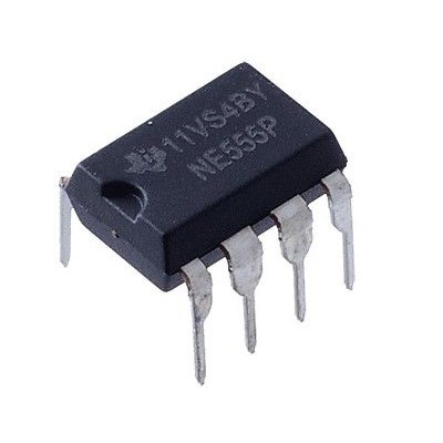
| 1. | IC | NE555 timer | 1 |
| 2. | Capacitor | 10µF | 2 |
| 3. | Resistor | 47K | 1 |
| 4. | Speaker | 8 ohm | 1 |
| 5. | Breadboard | – | 1 |
| 6. | Connecting wires | – | – |
| 7. | Battery | 9V | 1 |
NE555 IC Pinout

For a detailed description of pinout, dimension features, and specifications download the datasheet of 555 Timer
Tic-Tic Sound Generator Circuit

Working Explanation
A clear example of a 555-timer IC in Astable mode is the Ticking Sound Circuit. In this case, we are using an electronic signal converter. We do not use PIN 7 discharge and have the C2 capacitor attached to 555 IC’s OUTPUT PIN 3. In general, we link to the capacitor via resistors from the voltage source.
We connect the capacitor C2 directly via a power resistance of 47k ohm to the OUPUT PIN 3. When the PIN 3 output is HIGH, the capacitor is charged by the output. When PIN 3 is LOW, the capacitor C2 is unloaded to the speaker. The speaker produces a TIC-TIC sound like the capacitor charges and discharges.
Applications and Uses
the speaker generates the sound of TIC-TIC, as capacitor charge and discharge.


