Overview
Imagine you’re an electronics enthusiast tasked with testing various thyristors for a project. You’ve gathered different types of thyristors, including standard thyristors and triacs, and you’re eager to ensure they function as expected. However, testing these components can be tricky without the right tools. This is where the Thyristor Tester Circuit comes into play. It’s a straightforward yet powerful tool designed to quickly and accurately test different types of thyristors, making your testing process efficient and hassle-free
In today’s tutorial, we are going to make a “Thyristor Tester Circuit“.
Hardware Components
You’ll need the following hardware components to get started:
| S.no | Components | Value | Qty |
|---|---|---|---|
| 1 | Switches | S1, S2, S2, S4 | 1 |
| 2 | Capacitors | C1 ,C2 = 100n | 2 |
| 3 | Resistors | R1 ,R2 = 150Ω R3 = 33Ω R4 = 680Ω | 2 1 1 |
| 4 | LED’s | D1,D2 = Red Green | 1 |
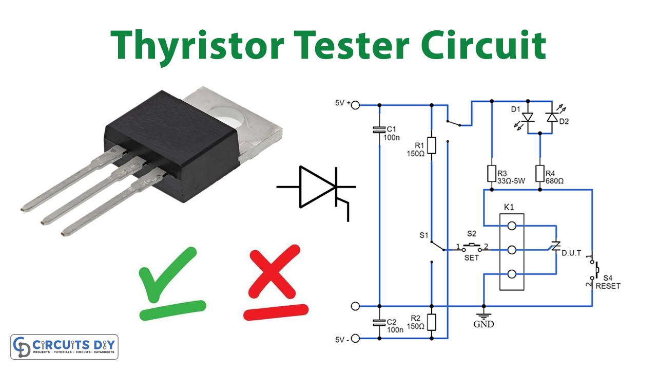
Schematic

The circuit shown in the diagram is a highly useful tool for quickly testing various types of thyristors (SCR, triac, etc.). For triacs, all four quadrants undergo testing using S3, while standard thyristors require setting a positive power supply and trigger current using S1. Resistor values for R1 and R2 are selected to achieve a current of approximately 28 mA, more than ample for most thyristors. R3 determines the hold current, set at 125 mA, sufficient to maintain thyristor conduction post-triggering. The LEDs, D1 (red, low-current) and D2 (green, low-current), indicate the conducting quadrant of the thyristor at a glance.
To initiate testing, press S2, and upon completion, reset the circuit using S4. For convenient connectivity, utilize three short lengths of circuit wire with insulated crocodile clips on connector K1 to link any type of thyristor to the circuit. Ensure correct connections: for a triac, connect MT1/A1 to earth, the gate to S2, and MT2/A2 to R3; for a standard thyristor, connect the anode to R3, the cathode to earth, and the gate to S2. If necessary, modify the trigger current by adjusting resistor values R1–R3 accordingly. Alternatively, use a variable power supply to vary the trigger current, but ensure that resistor dissipation limits are not exceeded.