Introduction
Printed circuit boards are vastly used for electronic devices. For the execution of electronic circuits, the designer chooses the best quality circuit board. So, to make the circuit secure and efficient, the designer uses printed circuit boards. But, before the invention of PCB end-to-end formation or point-to-point assembling was common. However, it was not effective and very unreliable. To make the circuits more efficient, designers took the idea of making PCB boards. Now, In today’s electronics world of PCB, there are commonly two types of technologies used, surface mount technology, and through-hole technology. In this article, we’ll do a comparison between them.
JLCPCB is the foremost PCB prototype & manufacturing company in china, providing us with the best service we have ever experienced regarding (Quality, Price Service & Time).
Through-Hole Technology
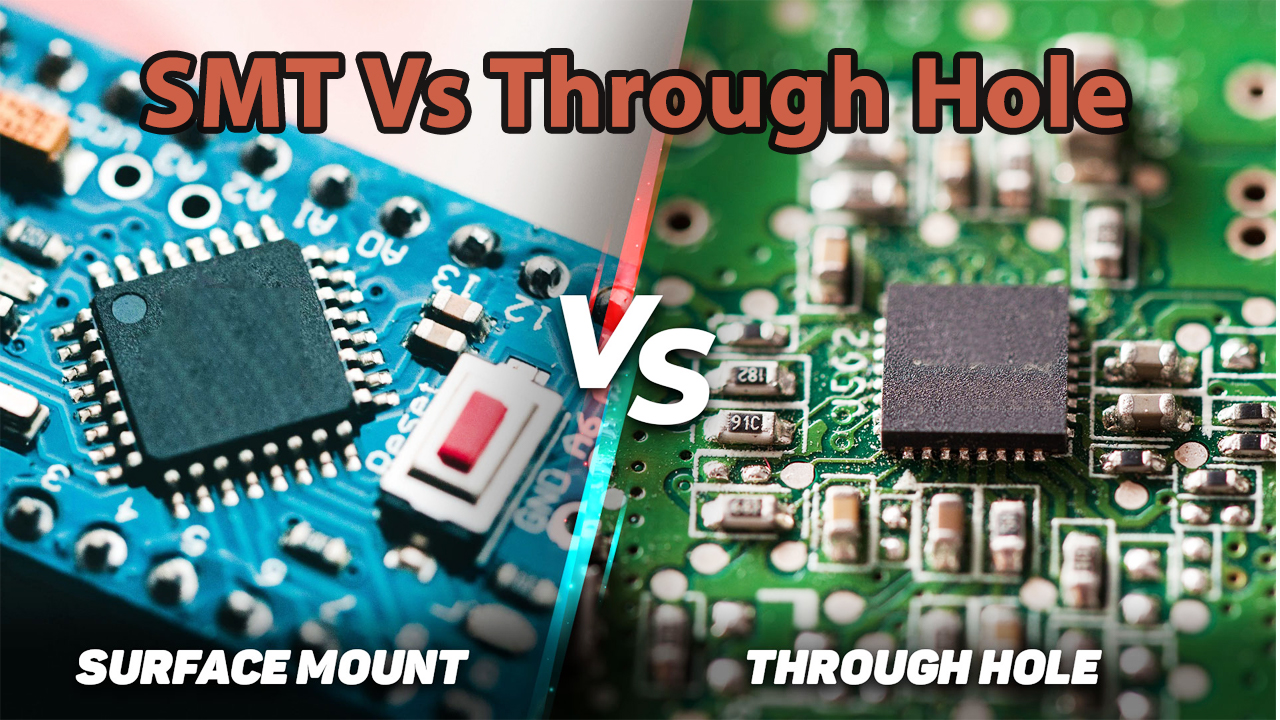
Through-hole was the technique that diminishes the point-to-point assembling method. It’s a mounting strategy that uses the leads on the components that get inserted into the Printed circuit boards. These are the components that are soldered automatically by machines or manually by hands. Thus, the technique is usually used for heavier components. Moreover, this technique is favorable for the prototype PCB as it’s inexpensive and reasonable.
Advantages of Through Hole
- This technology builds a strong bond between the board and the components.
- The board can carry and hold heavier and larger components.
- It can resist environmental stress.
- These kinds of the board can experience higher temperatures.
- They are relatively durable.
Surface Mount Technology
In the SMT procedure, the components are mounted directly on the surface of the Printed circuit boards. However, it increases the risk of errors because of the denser packing of the PCB board. The SMT has usually smaller components. It involves small leads or no leads at all.
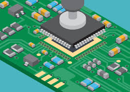
Advantages of Surface Mount
- It has a high assembly density, leading electronic devices to less weight.
- It contains high vibration resistance.
- SMT keeps greater reliability and durability rate.
- SMT has a high frequency that reduces electromagnetic and RF reduction.
- It requires a fewer number of soldering points.
- This technology saves the cost of the device.
Components of SMT and THT
SMT and THT have the main components that are described below:
- Passive components: The most common examples of this are the resistors and the capacitor. However, they also contain coils. These are for the devices that require a significant amount of power
- Transistors and Diodes: These are very small. Also, transistors have three legs, which makes them easy to solder.
- Integrated Circuits: Integrated circuits are of different kinds. Some have 8 pins, some of having 14 pins, some have more than that, and some that have microprocessors can have 200 pins or more. SMT has reduced the size while giving them all the features and power that belongs to them
Difference Between THT and SMT
| Through-Hole Technology | Surface Mount Technology |
| The soldering is performed manually or automatically. | Soldering is automated |
| No pads or vias | It comprises vias and pads |
| This contains only the Through-hole test point | It can have both kinds of test points including THT or SMT |
| Needs larger footprints | Requires fewer footprints |
| Two-sided assembly is not common | Commonly used two-sided assembling |
| No stencils required | It needs stencils |
Conclusion
SMT assembly is more reliable and efficient. On the other hand, requires knowledge of the whole process. Also, it has certain demands for the design phase. SMT makes productive and effective designs. But, additional drilling makes the board more expensive and less affordable. It can assemble more components in a smaller place. As a result, it saves money and reduces error. So, we have concluded that PCBs are still it’s growing day by day. Both the surface mount technology and through-hole technology of PCBs have their pros and cons.


