This is the project of a temperature-controlled switch using LM35 and CA3140 ICs. The main purpose of this circuit is to provide temperature sensing applications. LM35 is a temperature sensor IC, its output is linearly proportional to the temperature i.e., increases with the increase in temperature. It has low self-heating features and can operate at lower voltages and consumes less current which makes it ideal for battery operations. This IC is a readymade output temperature sensor and the calibration is accurately done by the manufacturer so it doesn’t require any calibration.
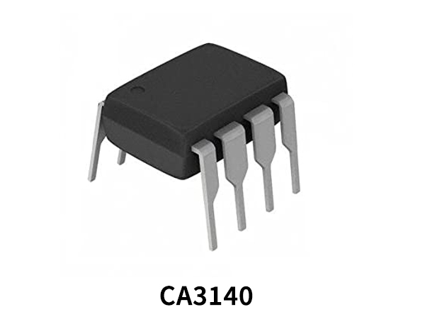
The other IC CA3140 is a BiMOS op-amp IC. It has combined advantages of PMOS transistors and bipolar transistors on a single monolithic chip. We are using this IC in the comparator mode in this circuit.

Hardware Components
The following components are required to make Temperature Controlled Switch Circuit
| S.no | Component | Value | Quantity |
|---|---|---|---|
| 1. | IC | CA3140 | 1 |
| 2. | IC | LM35 | 1 |
| 3. | Resistor | 470Ω | 1, 1 |
| 4. | LED | – | 1 |
| 5. | Relay | – | 1 |
| 6. | Diode | 1N4007 | 1 |
| 7. | Variable Resistor | 10K | 1 |
| 8. | DC Supply | 5-12V | 1 |
CA3140 Pinout

For a detailed description of pinout, dimension features, and specifications download the datasheet of CA3140
LM35 Pinout

For a detailed description of pinout, dimension features, and specifications download the datasheet of LM35
Temperature Controlled Switch Circuit

Working Explanation
The operating voltage of this circuit is 5 to 12 volts. When the temperature is sensed by te\he LM35 IC it sends an input signal to the second IC CA3140, this will turn on the LED and the relay. The relay switch is connected at the output of this circuit and you can control or switch ON & OFF any DC appliance with it on the desired temperature level of under 120 degrees Celsius. A variable resistor of 10K is used to adjust the desired temperature at which you want your circuit to activate. LED is also used here for the visual indication when the temperature is reached at the desired levels and the relay switch is on. The relay and the LED are connected at the output pin#6 of the CA3140 IC, you can also connect a buzzer instead if desired.
Applications and Uses
Different electronic appliances such as fans, LEDs, Lamps, Bells, etc. can be operated and controlled with this circuit according to the temperature


