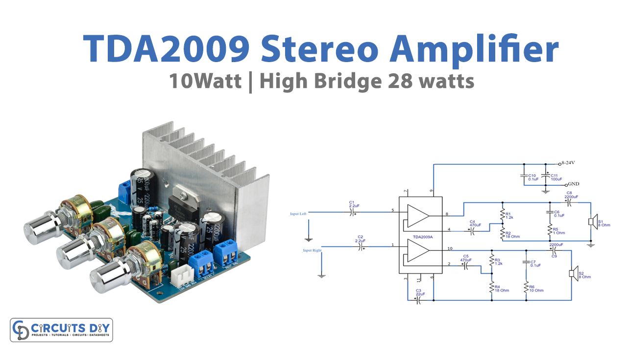
As we know, A stereo amplifier is an electronic device that amplifies an audio signal so that it may be heard properly via your speakers. They work by increasing the inadequate audio output from the source to a level sufficient to power your speakers. Stereo amplifiers can be made using different methods for different output power as required. Thus, In this Tutorial, we are going to make a “TDA2009 Stereo Amplifier Circuit”.
In the making of the circuit, we are using a 10W stereo amplifier IC TDA2009. The TDA2009A is a class AB dual Hi-Fi Audio power amplifier intended specifically for high-quality stereo applications such as Hi-Fi and music centers.
Hardware Required
| S.no | Component | Value | Qty |
|---|---|---|---|
| 1. | IC | TDA2009 | 1 |
| 2. | Resistor | 1.2K,18 ohm,10ohm,1 ohm | 2,2,1,1 |
| 3. | Capacitor | 2.2uF, 22uF, 470uF, 0.1uF, 100uF, 2200uF | 2, 1, 2, 3, 1, 2 |
| 4. | Speaker | 8 ohm | 2 |
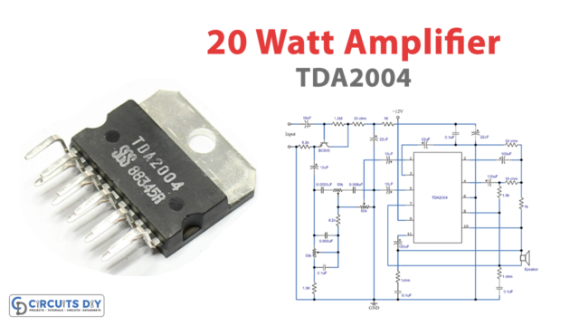
Circuit Diagram
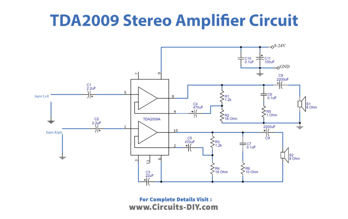
Working Explanation
First, connect the TDA2009 Amplifier stereo 10W circuit to the power supply. The audio signal should then be sent into the input. Both the left and right channels are identical. Capacitors C1 and C2 are input coupling capacitors that block DC to input pin 8 and non-inverting input pin 1. C8 and C9 are the output coupling capacitors. C4 and C5 prevent DC from entering the feedback loop. The feedback level is determined by the resistors R1/R2 (and R3/R4). 1+(R1/R2) = 68, or 37 dB, is the gain. Then, for stability, capacitors, and resistors C6/R5 (and C7/R6) are connected to a high-frequency load If the inductive reactance of the loudspeaker is excessive. Furthermore, C10 and C11 increase power supply filtering.
Application Uses
- For high-quality stereo applications
- Hi-Fi music devices