Motor driver modules are devices that control motors in autonomous robots and integrated circuits. A motor driver is undeniably anything that causes the motor to move in response to orders or inputs, both high and low. It leverages the low voltage from the controller/processor to power an actual motor that needs a high input voltage. In simple words, a motor driver controls the direction of the motor in response to orders or instructions from the controller. Before providing signals to the motors, the motor driver transforms signals from the microprocessor.
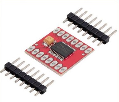
Overview of TB542A1
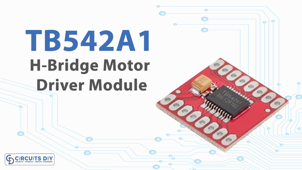
Up to two DC motors can be controlled by this Motor Driver at a constant current of 1.2A. They may control the motor using two input signals (IN1 and IN2) in one of four function modes: CW, CCW, short-brake, and stop. The speed of each motor is controlled by a PWM input signal with a frequency of up to 100kHz, and the two motor outputs (A and B) may be controlled individually. To bring the engine out of standby mode, pull the STBY pin high.
Features and Specifications of TB542A1 Motor Driver Module
Features
- Standby control to save power
- CW/CCW/short-brake/stop motor control modes
- Built-in thermal shutdown circuit and the low-voltage detecting circuit
- All pins of the TB6612FNG broken out to 0.1″ spaced pins
- Filtering capacitors on both supply lines
Specifications
- Power supply voltage: VM = 15V max, VCC = 2.7–5.5V
- Output current: Iout = 1.2A (average) / 3.2A (peak)
Applications of Motor Driver Module
Robotics
The motor driver can control DC motors using Microcontroller. You can drive a DC motor forward or backward using H-bridge integrated circuits (ICs). This is especially useful when you are working on robots like robotic cars, etc.
Stepper and DC Motors
The Motor Driver Module is a medium-power motor driver that works well with DC and stepper motors. It makes use of the well-known L293 motor driver IC. It can turn on and off four DC motors or regulate the speed and direction of two DC motors.

