Sound-activated switches are designed to provide a mechanism through which one can turn on or off any electrical appliance remotely through sound. Audio signal received through a microphone is amplified and compared with a specific threshold voltage to detect the occurrence of sound events.
This project uses an LM386 audio amplifier IC with a few other components to build a simple and accurate sound-activated alarm circuit. The circuit will activate a buzzer for a few seconds when the microphone receives a sound. The sensitivity of the circuit is good and it can detect sounds of the whistle, clap or finger snap from many meters away.

Hardware Components
The following components are required to make an activated Switch Circuit
| S.no | Component | Value | Qty |
|---|---|---|---|
| 1. | Breadboard or Vero board | – | 1 |
| 2. | Battery | 9v-12V | 1 |
| 3. | IC | LM386 | 1 |
| 4. | Optocoupler | PC817 | 1 |
| 5. | Piezo buzzer | – | 1 |
| 6. | Electrets Mic | – | 1 |
| 7. | Polar capacitors | 10µF, 100µF, 470µF | 1 |
| 8. | Resistors | 10K, 1K, 390Ω | 1 |
| 9. | Non polar capacitor | 100nF | 1 |
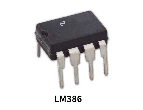
LM386 Pinout

For a detailed description of pinout, dimension features, and specifications download the datasheet of LM386
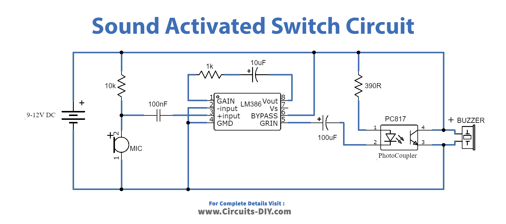
Sound Activated Switch Circuit

Working Explanation
The most important component of this circuit is the LM386 audio amplifier IC. An LM386 is a very popular and widely used audio amplifier IC that permits a user to amplify sound. LM386 chip comprises 8 pins where pins 1 and 8 denote the gain control of the amplifier, and you can adjust the gain by placing a resistor or capacitor in between these two terminals. The sound signal received by the electric Mic is converted into electrical audio signals. The sensitivity of the circuit is adjusted by a 10 µF capacitor along with a 1K resistor. These electrical audio signals are amplified by the LM386 and available at its output pin5. The amplified signal is then filtered by a 100uF capacitor and fed to the PC817 photocoupler, due to which the transistor in the photocoupler becomes actuated and charges the 470uF capacitor and activates the buzzer. The circuit requires an operating DC voltage of 9V to 12V.
Applications and uses:
Sound-activated switches are designed to provide a mechanism through which one can turn on or off any electrical appliance remotely through sound. It could be great for blind people as they don’t need to find the switch. It can also be used in toys for children.


