Introduction
Interfacing a water level sensor with an Arduino Uno is a popular and practical project for anyone interested in measuring and monitoring the water level in tanks, pools, and other liquid storage containers. By utilizing a water level sensor with an Arduino Uno, you can easily and accurately measure the liquid level and program the Arduino to take specific actions based on the level measurements. This opens up a wide range of possibilities for water level monitoring and control, from automating water pumping to alerting users when the water level is low. Whether for personal or industrial use, interfacing a water level sensor with an Arduino Uno is a powerful tool for managing liquid levels.
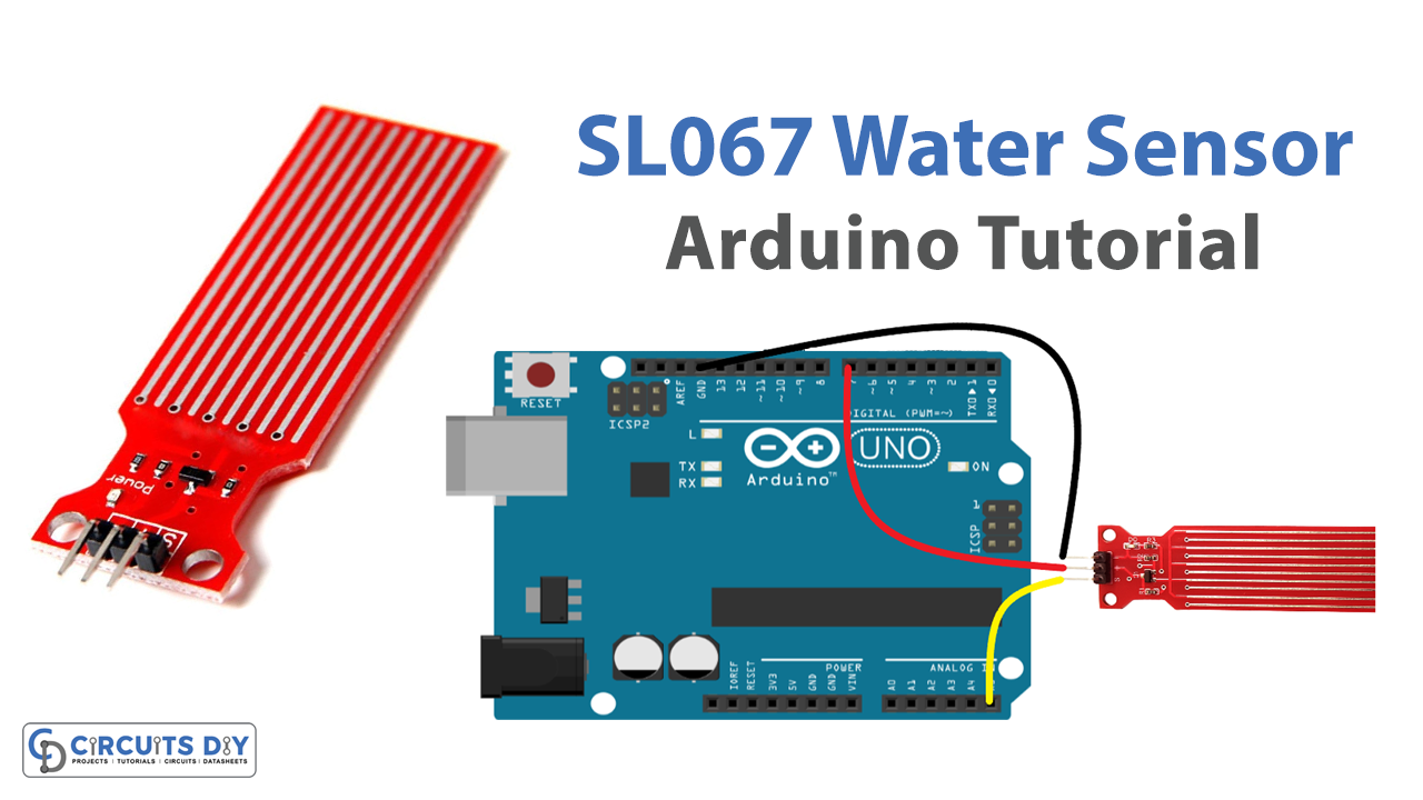
The Solu SL067 is a capacitive water level sensor module that can detect the water level of a tank or any other container. It works by measuring the capacitance between the electrodes of the sensor and the water, which changes as the water level rises or falls. This sensor is compatible with various microcontrollers, including the Arduino Uno. It has a wide detection range, can measure water levels up to 1.5m, and operates at a voltage of 5V DC. The sensor can detect the water level with high accuracy and has a simple interface with only two pins: a power supply pin and an analog output pin.
Hardware Components
You will require the following hardware for Interfacing Water Sensor with Arduino.
| S.no | Component | Value | Qty |
|---|---|---|---|
| 1. | Arduino UNO | – | 1 |
| 2. | USB Cable Type A to B | – | 1 |
| 3. | Water level sensor | – | 1 |
| 4. | Power Adapter for Arduino | 9V | 1 |
| 5. | Jumper Wires | – | 1 |
Steps Interfacing Water Sensor with Arduino UNO
- It defines two constants: POWER_PIN and SIGNAL_PIN. POWER_PIN is the digital pin on the Arduino board that controls the sensor’s power supply. SIGNAL_PIN is the analog pin on the Arduino board that reads the sensor’s output signal.
#define POWER_PIN  7
#define SIGNAL_PIN A5
- It declares a variable “value” to store the sensor’s output signal.
int value = 0;
- In the setup() function, it initializes the serial communication and configures the POWER_PIN as an output. It sets the initial state of the POWER_PIN to LOW, which means the sensor is initially turned off.
void setup() {
  Serial.begin(9600);
  pinMode(POWER_PIN, OUTPUT);
  digitalWrite(POWER_PIN, LOW);
}
- In the loop() function, it turns the sensor on by setting the POWER_PIN to HIGH, waits for 10 milliseconds, reads the analog value from the SENSOR_PIN, and turns the sensor off by setting the POWER_PIN to LOW.
void loop() {
  digitalWrite(POWER_PIN, HIGH);
  delay(10);
  value = analogRead(SIGNAL_PIN);
  digitalWrite(POWER_PIN, LOW);
}
- It prints the value of the sensor to the serial monitor.
Serial.print("Sensor value: ");
Serial.println(value);
- It adds a delay of 1 second before repeating the loop() function.
delay(1000);Schematic
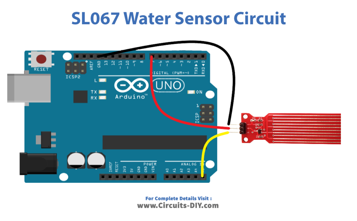
Make connections according to the circuit diagram given below.
Wiring / Connections
| Arduino | Water Sensor |
|---|---|
| D7 | VCC |
| GND | GND |
| A5 | SIG |
Installing Arduino IDE
First, you need to install Arduino IDE Software from its official website Arduino. Here is a simple step-by-step guide on “How to install Arduino IDE“.
Code
Now copy the following code and upload it to Arduino IDE Software.
#define POWER_PIN  7
#define SIGNAL_PIN A5

int value = 0; // variable to store the sensor value

void setup() {
  Serial.begin(9600);
  pinMode(POWER_PIN, OUTPUT);   // configure D7 pin as an OUTPUT
  digitalWrite(POWER_PIN, LOW); // turn the sensor OFF
}

void loop() {
  digitalWrite(POWER_PIN, HIGH);  // turn the sensor ON
  delay(10);                      // wait 10 milliseconds
  value = analogRead(SIGNAL_PIN); // read the analog value from sensor
  digitalWrite(POWER_PIN, LOW);   // turn the sensor OFF

  Serial.print("Sensor value: ");
  Serial.println(value);

  delay(1000);
}
Working Explanation
The code begins by defining a constant value for the power pin (D7) and the analog input signal pin (A5). The variable value is initialized to zero, which will be used to store the analog value from the sensor. The setup() function initializes the serial communication at 9600 baud rate and configures the power pin as an output, and turns the sensor off.
The loop() function begins by turning on the sensor by setting the power pin high, waiting 10 milliseconds for the sensor to stabilize, and then reading the analog value from the sensor using the analogRead() function. The sensor is then turned off by setting the power pin low, and the value read from the sensor is printed to the serial monitor using the Serial.println() function. A delay of 1 second is added to the loop to prevent the sensor from being read too frequently.
Applications
- Tank level monitoring
- Flood detection
- Water quality monitoring
- Irrigation control
- Automatic watering systems for plants
- Aquarium water level monitoring
- Monitoring water usage in industrial processes
- Home automation projects
Conclusion.
We hope you have found this Water Sensor Circuit very useful. If you feel any difficulty in making it feel free to ask anything in the comment section.


