
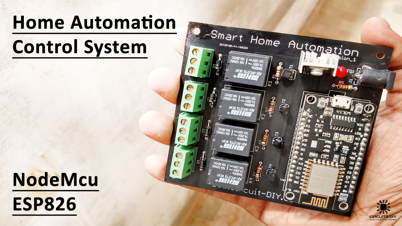
Hey guys, how are you doing?. This weekend when I was pondering about what exciting I can build, on the Esp NodeMcu board, I was struck by an idea, why not build an awesome home automation module which is compact and packed with features to help you control your home appliances from anywhere in the world. So in this tutorial, I am going to show you step by step How to make a “Smart Home Automation Control System using NodeMcu ESP8266 Microcontroller”
Home Automation?
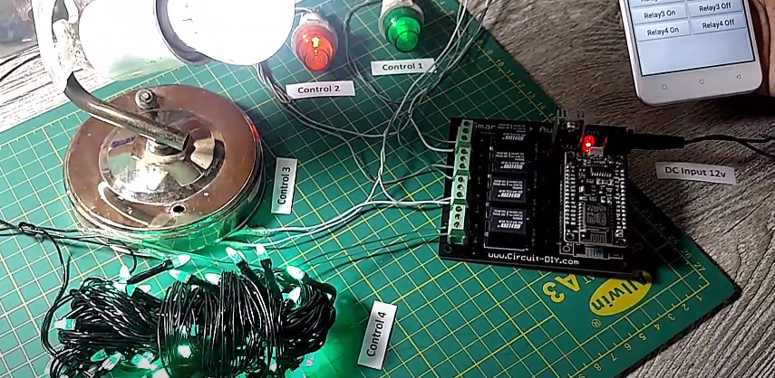
Home automation refers to the ability of your home to make its own decisions depending on environmental conditions and gives you the option to control it from a remote location. This Smart Home Automation Kit is specially designed to control AC appliances of your home by using an android app. It has four relays that are operating on digital signals coming from NodeMcu. Both of these devices (NodeMcu & Android App) are connected with the Firebase Cloud Database of google.
PCBWay commits to meeting the needs of its customers from different industries in terms of quality, delivery, cost-effectiveness, and any other demanding requests. As one of the most experienced PCB manufacturers in China. They pride themselves to be your best business partners as well as good friends in every aspect of your PCB needs.
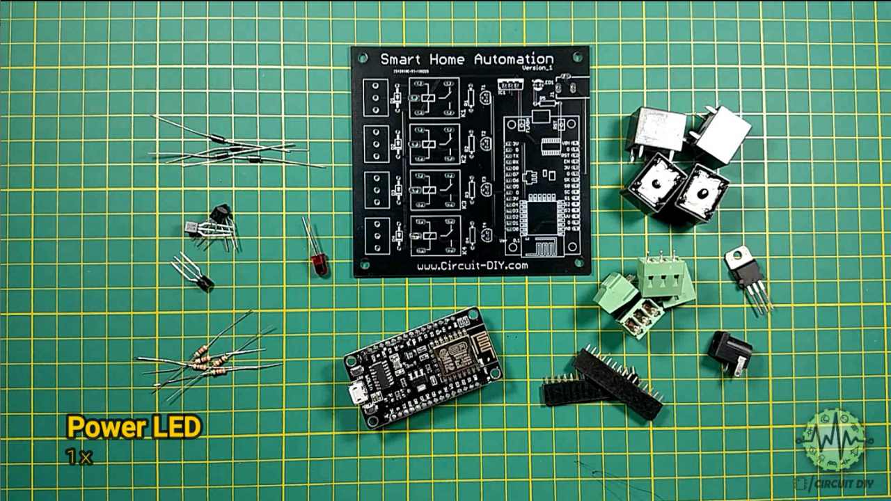
Hardware Components
The following are the necessary hardware items required for smart home automation system.
| S.no | Components | Value | Qty |
|---|---|---|---|
| 1. | PCB Smart Home Automation | – | 1x |
| 2. | NodeMcu | ESP8266 | 1x |
| 3. | Relay | 5V | 4x |
| 4. | Diodes | 1N4007 | 4x |
| 5. | Resistors | 330 Ohm | 5x |
| 6. | NPN Transistors | BC547 | 4x |
| 7. | Terminal Block | 5mm | 4x |
| 8. | Regulator | LM7805 5V | 1x |
| 9. | Power LED | – | 1x |
| 10. | DC Power Jack | – | 1x |
| 11. | Power Supply | 12 Volt | 1x |
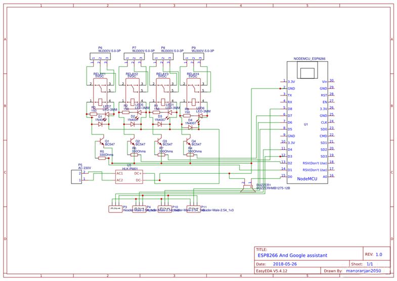
Circuit Diagram
Circuit Construction
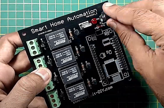
Step 01 (Fixing and Soldering)
Fix all the hardware components on the PCB board. Make sure to attach the components on the destinated slots available on PCB board. After placing all the components at their destinated place, carefully solder them all.
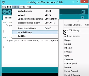
Step 02 (Setting up Arduino IDE)
Download both of the library “ArduinoJson” and “Firebase-Arduino-master” files and add them in Arduino library. Link to download these concerned files are attached below.
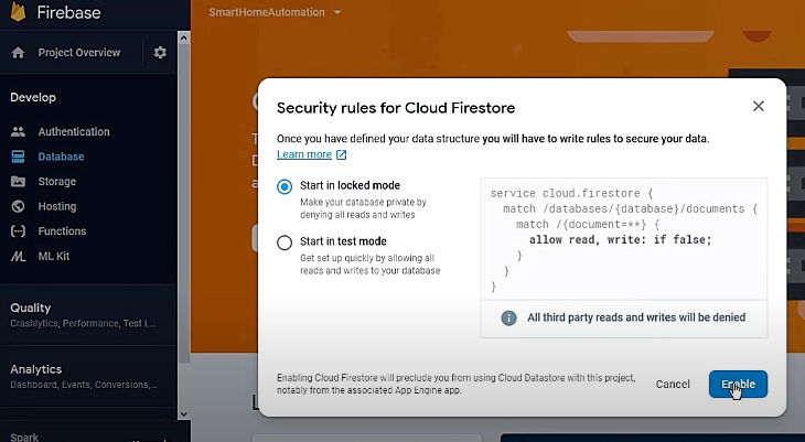
Step 03 (Setting up Firebase)
Go to the Firebase Console https://console.firebase.google.com/ and login via your email. After a successful login to the site, enter your project name by clicking on the “Add Project” option. Then create a project database, and enables it on “Locked mode”. Now, in the top left corner change the option to “Realtime Database” and let the database generate firebase code. Do some small changes in the code as mentioned in the video above. Copy the database URL and update it on the Arduino code. Make sure to remove “Http: and //” from the updated Arduino code. Now get back to the firebase server, and Go to Project settings, copy authentication code and update it on the Arduino code. Now update wifi SSID and password in the Arduino code. Update the code and upload it to the hardware setup.
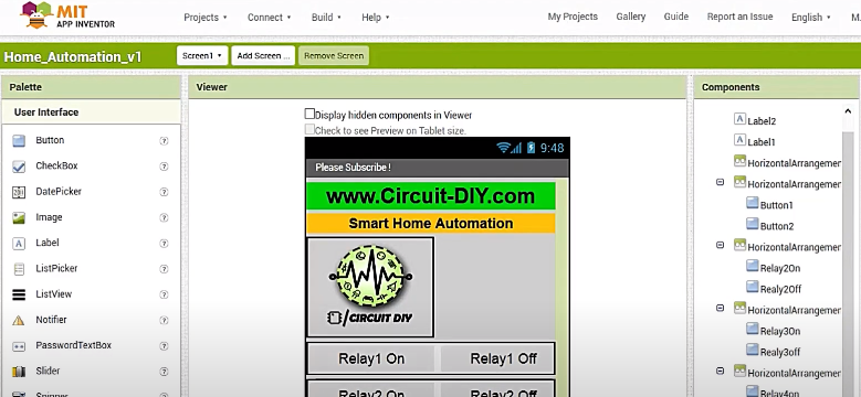
Step 04 (Setting up IoT App)
Search for “MIT App Inventor 2” in the google search bar. Sign in via your email, and import the given “ai” file. Follow the instructions as mentioned in the video tutorial above. Click on the firebase icon and update the firebase URL and authentication code in their destined places. Build the project, and now your Smart Home Automation system is ready to test!
Step 05 (Testing)
Now test the circuit via your Android phone, Check the operation of each relay associated with the circuit by pressing “On” and “Off” buttons.
Working Explanation
The core component of this “Smart Home Automation system” is Node MCU which is considered as a brain or controlling device of the system. The data sent from the IoT Android App to the Firebase realtime database, which is hosted in the cloud. The transmitted data is then received by the wifi module connected with the Node MCU. Hence, the Node MCU receives and interprets the received data and performs the switching operation of electrical devices that are connected with the Relays.
Code
#include#include #define FIREBASE_HOST "basic-2db74.firebaseio.com" // Your Firebase Project URL goes here without "http:" , "\" and "/" #define FIREBASE_AUTH "WljQ8JpTdYqUAnp7VCPgcOshaL90zJtvW83NHAov" // Your Firebase Database Secret goes here #define WIFI_SSID "TP-LINK_CD2ED6" // your WiFi SSID for which yout NodeMCU connects #define WIFI_PASSWORD "20244064" // your WiFi PASSWORD #define Relay1 12 //D6 int val1; #define Relay2 14 //D2 int val2; #define Relay3 4 //D1 int val3; #define Relay4 5 //D5 int val4; void setup() { Serial.begin(115200); // Select the same baud rate if you want to see the datas on Serial Monitor pinMode(Relay1,OUTPUT); pinMode(Relay2,OUTPUT); pinMode(Relay3,OUTPUT); pinMode(Relay4,OUTPUT); digitalWrite(Relay1,HIGH); digitalWrite(Relay2,HIGH); digitalWrite(Relay3,HIGH); digitalWrite(Relay4,HIGH); WiFi.begin(WIFI_SSID,WIFI_PASSWORD); Serial.print("connecting"); while (WiFi.status()!=WL_CONNECTED){ Serial.print("."); delay(500); } Serial.println(); Serial.print("connected:"); Serial.println(WiFi.localIP()); Firebase.begin(FIREBASE_HOST); Firebase.setInt("S1",0); //Here the varialbe"S1","S2","S3" and "S4" needs to be the one which is used in our Firebase and MIT App Inventor Firebase.setInt("S2",0); Firebase.setInt("S3",0); Firebase.setInt("S4",0); } void firebasereconnect() { Serial.println("Trying to reconnect"); Firebase.begin(FIREBASE_HOST); } void loop() { if (Firebase.failed()) { Serial.print("setting number failed:"); Serial.println(Firebase.error()); firebasereconnect(); return; } val1=Firebase.getString("S1").toInt(); //Reading the value of the varialble Status from the firebase if(val1==1) // If, the Status is 1, turn on the Relay1 { digitalWrite(Relay1,LOW); Serial.println("Relay 1 ON"); } else if(val1==0) // If, the Status is 0, turn Off the Relay1 { digitalWrite(Relay1,HIGH); Serial.println("Relay 1 OFF"); } val2=Firebase.getString("S2").toInt(); //Reading the value of the varialble Status from the firebase if(val2==1) // If, the Status is 1, turn on the Relay2 { digitalWrite(Relay2,LOW); Serial.println("Relay 2 ON"); } else if(val2==0) // If, the Status is 0, turn Off the Relay2 { digitalWrite(Relay2,HIGH); Serial.println("Relay 2 OFF"); } val3=Firebase.getString("S3").toInt(); //Reading the value of the varialble Status from the firebase if(val3==1) // If, the Status is 1, turn on the Relay3 { digitalWrite(Relay3,LOW); Serial.println("Relay 3 ON"); } else if(val3==0) // If, the Status is 0, turn Off the Relay3 { digitalWrite(Relay3,HIGH); Serial.println("Relay 3 OFF"); } val4=Firebase.getString("S4").toInt(); //Reading the value of the varialble Status from the firebase if(val4==1) // If, the Status is 1, turn on the Relay4 { digitalWrite(Relay4,LOW); Serial.println("Relay 4 ON"); } else if(val4==0) // If, the Status is 0, turn Off the Relay4 { digitalWrite(Relay4,HIGH); Serial.println("Relay 4 OFF"); } }
Project Files
Download all important project files for making this smart home automation from the link given in the description below. File Includes (Code, App, Circuit Diagram, Gerber File).
Related posts:
 How To Make An RFID Card Reader Without Using An Arduino
 How to make Audio Level Indicator - VU meter using LM3914 IC
 Automatic Street Night Light Circuit Using LDR | DIY Project
 Matrix Scrolling Weather Station & Clock
 Electric Field Strength Detector Using CD4011BE IC
 How to Make a Water Level Indicator using CD4511 & 74147 IC


1 thought on “Smart Home Automation System using NodeMcu ESP8266”
Comments are closed.