This tutorial will explain to you a simple temperature-controlled DC fan. The fan starts above the preset value of temperature and stops when the temperature returns to normal conditions. Such type of process is done automatically where temperature-controlled devices play an important role.
This circuit has plenty of applications in electronic projects which require a cooling fan. So it can be rightly said that automation is good, as long as you know exactly where to put the machine.
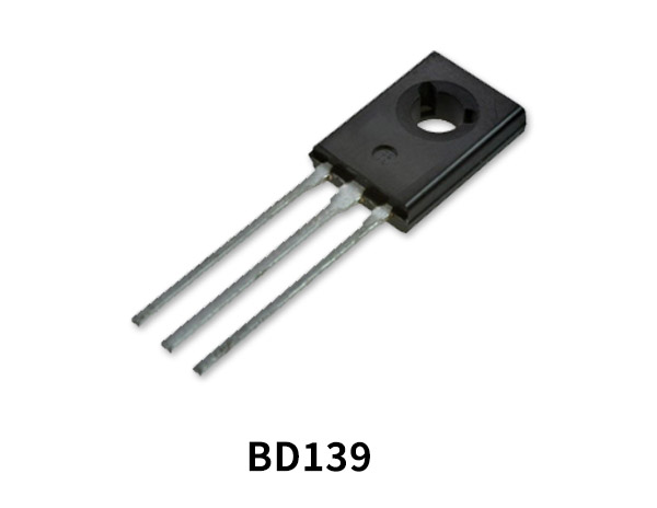
Hardware Components
The following components are required to make Temperature Controlled DC Fan Circuit
| S.No | Components | Value | QTY |
|---|---|---|---|
| 1 | DC Fan | 9-12v | 1 |
| 2 | Transistor | BD139 | 1 |
| 3 | Thermistor | 10k | 1 |
| 4 | Resistor | 1k | 1 |
| 5 | Potentiometer | 100k | 1 |
| 6 | Diode | 1N4007 | 1 |
| 7 | Battery | 12V | 1 |
| 8 | Breadboard | – | 1 |
BD139 Pinout

For a detailed description of pinout, dimension features, and specifications download the datasheet of BD139
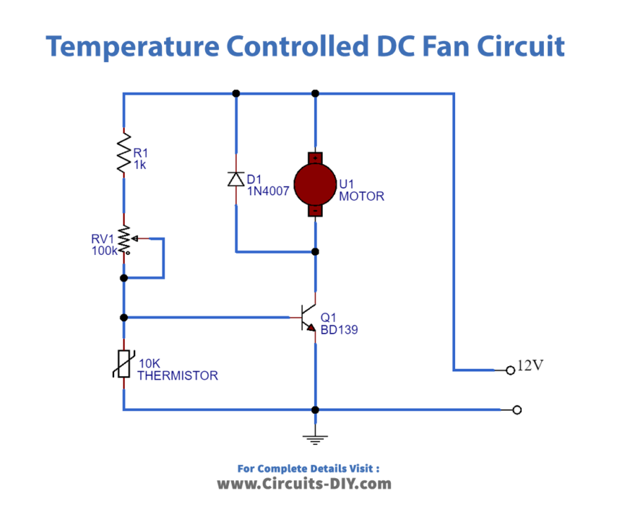
Temperature-Controlled DC Fan Circuit
Working Explanation
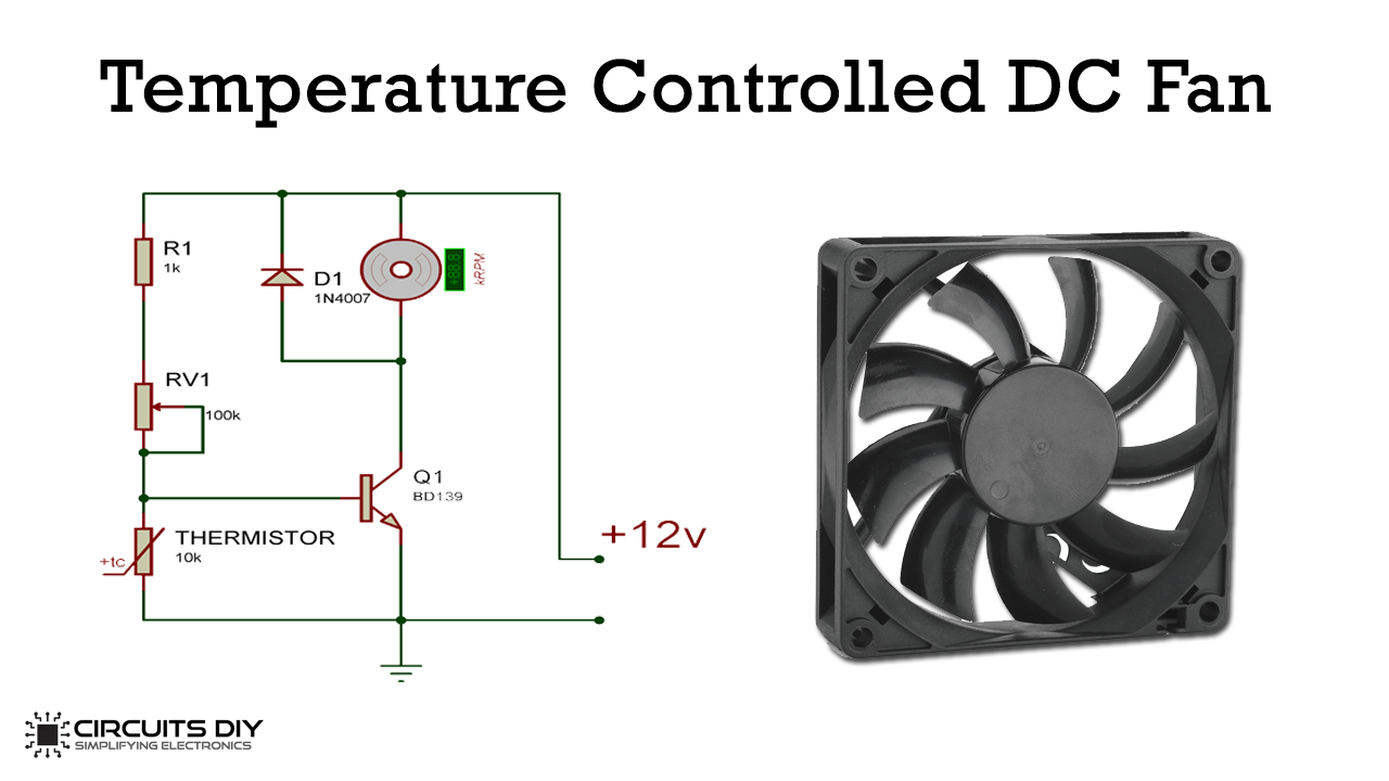
The design of a circuit is very simple and it requires a less number of components. The BD139 transistor operates as a switch here. In addition to this, the temperature-controlled sensor uses the NTC thermistor to control the temperature. So when the thermistor receives the heat its resistance starts decreasing. As it reaches the set value transistor turns on and activates the DC fan.
When the value temperature falls below the set value the transistor turns OFF which deactivates the DC fan. As the transistor also dissipates heat during its operation so make sure that there shall be enough distance between the thermistor and the transistor. Otherwise, the circuit will not function properly.
Application
- The temperature-controlled DC fan performs the function of cooling laptops and computers.
- The device also works for cooling the car engine.


