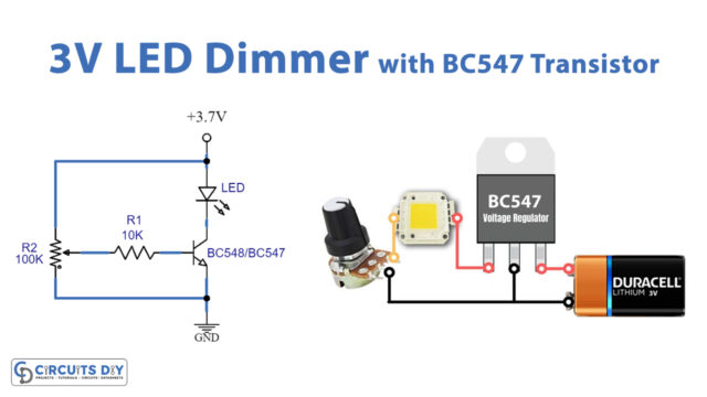
In this tutorial, we are demonstrating the project of an “LED Dimmer.” If you need to control the brightness of a couple of LEDs, at that point, this simple dimmer circuit will carry out the process. An “LED dimmer” is the device that controls the dimming activity within an LED device.
As we all know, LEDs are light-emitting diodes, which is a semiconductor, and when the current flows in them, it emits a light source. LEDs respond immediately to adjustments in power input, making solid-state lighting particularly proper for darkening situations.
Hardware Component
The following components are required to make LED Dimmer Circuit
| S.no | Component | Value | Qty |
|---|---|---|---|
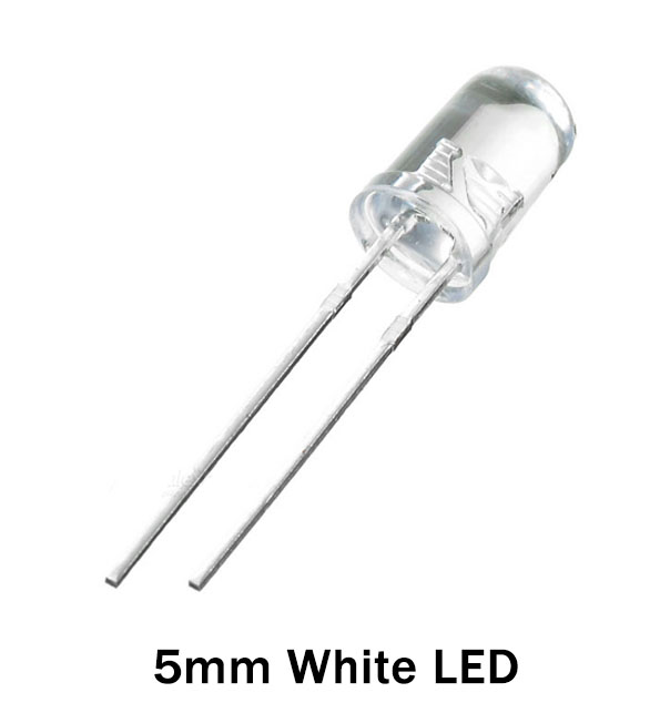
| 1. | LEDs | – | 3 |
| 2. | Potentiometer | 1K/ 1 to 2 Watt | 1 |
| 3. | DC Supply | 9V to 12V | 1 |
| 4. | Resistor | 56Ω 1W | 1 |
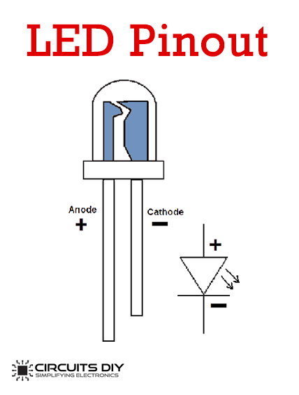
LED Pinout
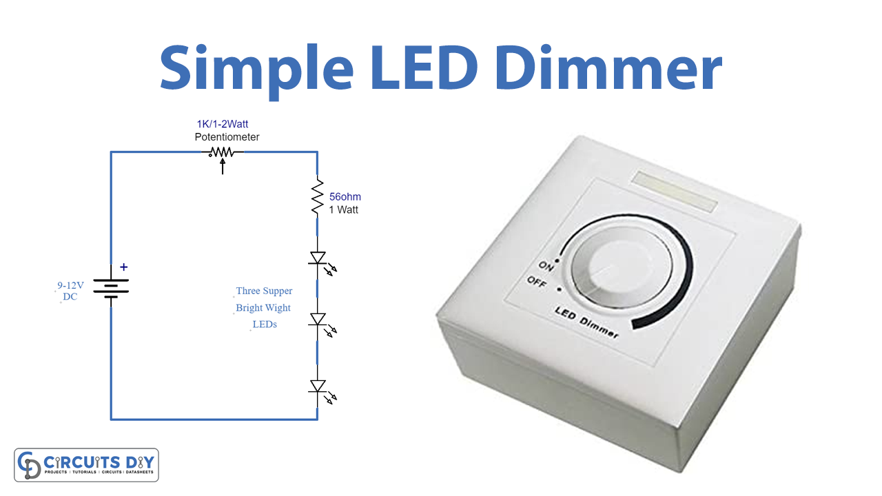
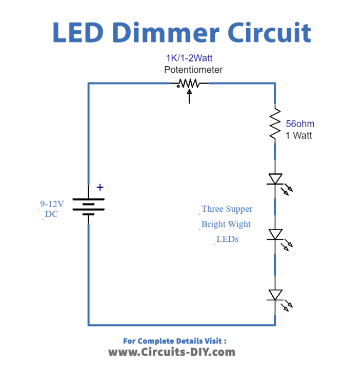
LED Dimmer Circuit
Working Explanation
The circuit is utilizing a 1K potentiometer of 1 or 2 watts to control the brilliance of LEDs. The circuit is likewise utilizing three very splendid white LEDs. I have used 0.5 watt LEDs for all the lights. The 56 Ohms 1-watt resistor is filling in as a current limiter and furthermore shields the LEDs from overcurrent when the potentiometer is without resistance. The circuit can be worked from 9 to 12 volt DC. You can likewise work the circuit with your vehicle battery. This basic LED dimmer circuit can likewise be utilized as a small-scale dimmable LED night lamp and furthermore as a 12V LED light when you require a smaller than normal LED light.
Applications and Uses
This simple LED Dimmer Circuit is used in
- Flash Lights
- Smartphones
- Navigation devices


